

Shop Drawing Services for General Contractors
Coordinate multiple building trades with professional shop drawings, submittal packages, and 3D clash detection tailored for American general contractors, construction managers, superintendents, and preconstruction teams. From structural steel and concrete embeds to MEP risers and architectural millwork, we help you eliminate field rework and maintain tight project schedules.
General Contractor Advantages
- Multi-Trade Drawing SupportCoordinate structural steel, concrete, MEP, and millwork within one cohesive environment.
- Organized Submittal PackagesPre-checked drawing sets with title blocks and logs matching CSI Section 01 33 00 registers.
- RFI & Revision CoordinationClear sketches clarifying discrepancies, with delta clouds and tracking for fast review.
- Nationwide Remote ServicesSupporting commercial, industrial, and institutional projects across all 50 US states.

Reliable Shop Drawing Support for General Contractors
In commercial building construction, general contractors carry ultimate responsibility for project delivery, trade handoffs, and schedule preservation. Architectural and structural contract drawings illustrate design intent, but they do not provide the exact fabrication dimensions, weld callouts, cut lengths, or spatial tolerances required by shop fabricators and field crews. General contractors depend on trade-specific shop drawings to bridge this divide.
Under standard US project workflows (such as AIA Document A201 and AGC submittal protocols), shop drawings must be systematically reviewed and verified by the general contractor before transmittal to the Architect of Record (AOR) and Engineer of Record (EOR). When detailing is handled in isolation by separate subcontractors, general contractors frequently battle uncoordinated gridlines, missing slab embeds, and mechanical penetrations conflicting with structural beams.
Our drafting and coordination services support general contractors by establishing unified project geometry, drafting clear RFIs when contract documents exhibit discrepancies, and applying strict delta revision controls. By coordinating scope packages prior to fabrication release, we help GC teams mitigate jobsite change orders and maintain field momentum.
The General Contractor’s Submittal Objective
Shop drawings are not merely contract compliance submissions; they are the primary tool general contractors use to lock down vendor pricing, verify dimensional clearances between subcontractors, and ensure fabrication proceeds from fully coordinated, approved documents.
Shop Drawing Support That Fits Your Construction Workflow
Designed around the daily operational demands of commercial project managers, superintendents, and preconstruction teams.
Organized Submittal Coordination
Drawing packages are formatted and scheduled to align with your project submittal register (CSI Section 01 33 00), including standardized sheet numbering, title block data, and revision histories.
Multi-Trade Drawing Support
Instead of managing isolated drafting shops, work with a single coordination partner across structural steel, concrete, miscellaneous metals, MEP, and millwork packages.
Clear RFI Documentation
When contract drawings contain dimensional conflicts or missing details, we provide concise RFI sketches illustrating the issue and proposing constructible options for design team review.
Revision Tracking & Delta Control
When plans are updated by bulletin, addenda, or RFI responses, we clearly cloud revisions and update delta blocks so your team and the EOR can track changes instantly.
Fabrication & Installation Detail
Drawings include unambiguous piece marks, anchor bolt setting plans, embedment depths, hole tolerances, and fastener schedules that give your field superintendents confidence during installation.
Remote Nationwide Coordination
Our team collaborates with general contracting teams across the US through cloud-based markups, scheduled screen shares, and secure digital file exchanges regardless of project location.
Shop Drawing Services Across Major Construction Trades
Select specialized trade drawings or assemble multi-trade coordination packages tailored to your commercial subcontractor buyout.

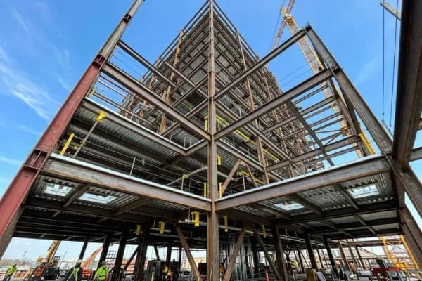
Structural Steel Shop Drawings
Framing plans, column assembly sheets, beam details, AISC moment connections, and erection plans.
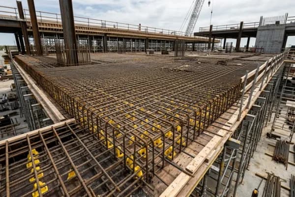
Concrete & Rebar Detailing
Reinforcing placement drawings, bar bending schedules (BBS), footing details, and embed layouts to ACI 318.

Miscellaneous Metals
Stairs, platforms, ladders, catwalks, canopies, dumpster gates, and architectural metal fabrications.

Architectural Millwork & Casework
Custom cabinetry, reception desks, wood paneling, trim packages, and hardware schedules conforming to AWI.

Glass & Glazing / Storefronts
Curtain walls, aluminum storefronts, glass canopies, entrance systems, and structural silicone glazing.
HVAC & Mechanical Shop Drawings
SMACNA-compliant ductwork routing, mechanical piping spools, equipment room layouts, and hanger details.
Plumbing Shop Drawings
Domestic water, sanitary waste, vent risers, gas piping, underground utilities, and sleeve penetration plans.

Electrical Shop Drawings
Conduit rack layouts, switchgear rooms, lighting installations, panel locations, and power routing to NEC.
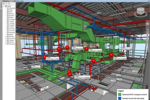
BIM Coordination & Clash Detection
3D federated model coordination, Navisworks clash resolution matrices, and pre-slab penetration coordination.
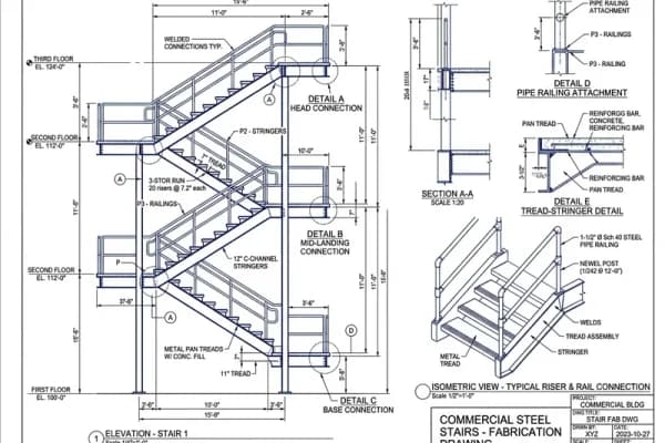
Stairs, Railings & Guardrails
Egress stair towers, monumental stairs, industrial pipe handrails, guardrails, and picket attachments to IBC.
Multi-Trade Shop Drawing Capabilities for Commercial Projects
Each construction trade requires distinct drawing standards, geometry, piece marks, and engineering boundaries. Here is how our team details each primary scope for general contractors.
Structural Framing & Miscellaneous Metals
Prepared in strict compliance with AISC 303-22 (Code of Standard Practice) and AISC 360 specifications. We generate general arrangement framing plans, member detail sheets, single-part shop drawings, and anchor bolt setting plans. Connection details cover standard shear tabs, moment connections, bracing gussets, and trusses. Miscellaneous metal scopes include egress stairs, industrial pipe railings, roof access ladders, elevator divider beams, and rooftop equipment support skids.
Concrete Reinforcement & Embeds
Conforming to ACI 318-19 and CRSI Manual of Standard Practice. We detail rebar placement plans for continuous footings, mat foundations, grade beams, reinforced columns, shear walls, and elevated slabs. Deliverables include complete bar bending schedules (BBS), lap splice schedules, clearance chair layouts, and concrete embed insert plans that ensure steel anchor bolts and structural weld plates are placed accurately prior to the concrete pour.
Mechanical & HVAC Coordination
Detailed according to SMACNA HVAC Duct Construction Standards (Metal and Flexible). We create fabrication drawings for rectangular, spiral, and oval ductwork, detailing sheet metal gauges, TDC/TDF joint flanges, acoustic lining thickness, turning vanes, fire/smoke damper sleeve placements, and CFM airflow tags. Coordinated drawings reflect true exterior duct insulation dimensions to resolve ceiling plenum conflicts with structural beams and lighting fixtures before shop cutting.
Plumbing & Piping Systems
Developed in conformance with the International Plumbing Code (IPC) and Uniform Plumbing Code (UPC). Drawings cover sanitary waste and vent risers, domestic cold/hot water distribution, gas piping, grease waste systems, and storm drainage. We detail pipe invert elevations, 1/4\" per foot gravity slope runs, floor drain trap primers, backflow preventers, and coordinated slab penetration sleeves so core drilling through post-tensioned or reinforced decks is avoided.
Electrical Equipment & Raceway Documentation
Detailing major electrical installations to the National Electrical Code (NEC NFPA 70). We coordinate feeder conduit racks, overhead cable trays, transformer pad dimensions, switchgear room footprints, and panel clearances. Floor penetration layouts and stub-up coordinates ensure that multi-tiered conduit runs do not interfere with underground plumbing mains or structural grade beams in electrical service rooms.
Millwork & Architectural Finishes
Prepared according to the Architectural Woodwork Institute (AWI) Architectural Woodwork Standards (AWS) Custom and Premium Grade. Our detailers provide full assembly drawings for commercial reception desks, kitchenette casework, laminate wall paneling, banquette seating, and solid surface countertops. Drawings detail substrate joinery, Blum hardware schedules, reveal dimensions, and MEP service cutouts.
Glass & Storefront Systems
Coordinated to AAMA/FGIA standards for commercial fenestration. We prepare complete shop drawing packages for aluminum storefronts, glazed curtain walls, interior glass partitions, and structural glass railings. Drawings detail head, sill, and jamb anchors, mullion splice locations, thermal barrier details, glass thickness and tint schedules, and perimeter sealant joints accommodating building thermal movement.
BIM Coordination & Model-Based Reviews
Utilizing Autodesk Revit and Navisworks Manage at Level of Development (LOD) 300 to 400. We assemble federated models integrating structural, architectural, MEP, and fire suppression geometry. We execute hard and soft clash detection tests, generate prioritized clash matrices for subcontractor coordination meetings, and produce coordinated combined services drawings (CSD) to resolve interferences pre-construction.
Our Shop Drawing Process for General Contractors
A disciplined five-step submittal workflow engineered to integrate smoothly with your project management and engineering review cycles.
Submit Project Documents
Send current architectural, structural, and MEP plans, project specifications, issued addenda, and your required submittal milestones.
Scope Review & RFIs
Our detailers audit the plans for missing dimensions, conflicting gridlines, and trade gaps. We draft sketches for GC review and RFI issuance.
Drawing Preparation
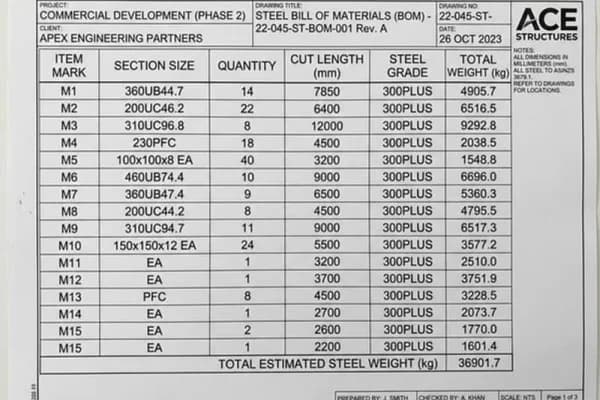
We generate 3D models and 2D CAD drawing sheets detailing member sizes, piece marks, weld symbols, clearances, and material bills.
Coordination & Review
The GC and design team review the submittal. We incorporate Architect and EOR markups, cloud all changes, and update delta blocks.
Final Shop Release
Upon receiving approved status, we deliver fabrication-ready drawing sets, bill of materials, CNC data files, and as-built coordination models.
General Contractor Shop Drawing Examples
Review conceptual drawing samples demonstrating our linework clarity, technical annotations, piece mark schedules, and dimensional precision across trades.
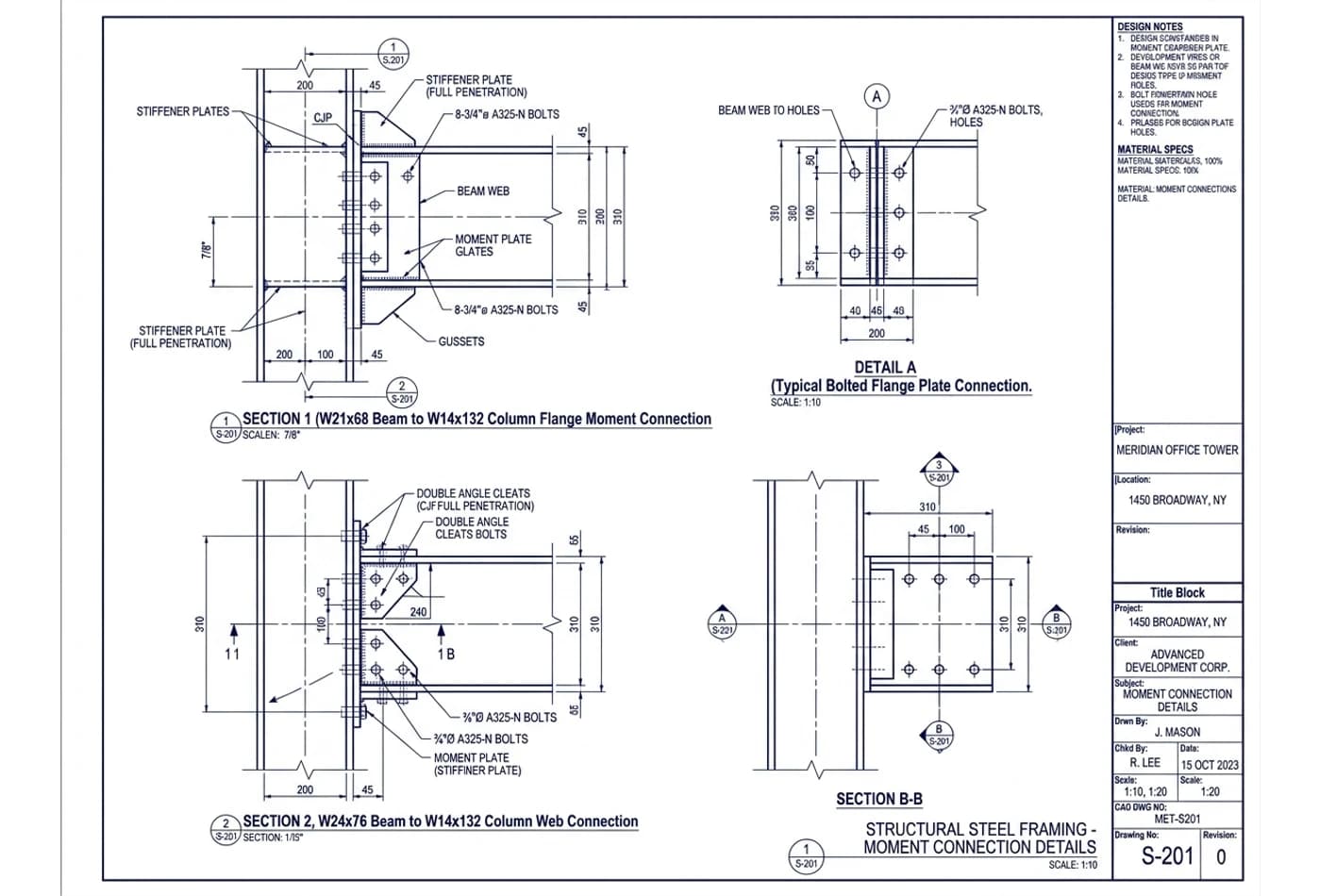
Structural Steel Framing & Moment Connection
Commercial office tower beam-to-column flange moment connection detail. Illustrates W21x68 beam framing into W14x132 column with full penetration CJP groove welds, stiffener plates, cope geometry, A325-N high-strength bolt patterns, and AISC 360-16 design notes.
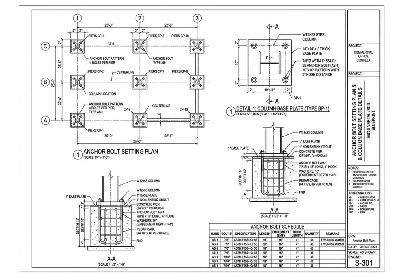
Reinforced Concrete Foundation & Embed Detail
Reinforced concrete pier foundation plan and anchor rod setting layout. Details ASTM F1554 Gr. 55 anchor rod hook depths, 14"x14"x1" base plate templates, #4 rebar ties, #6 vertical rebar cages, non-shrink grout clearances, and concrete embedment dimensions to ACI 318.
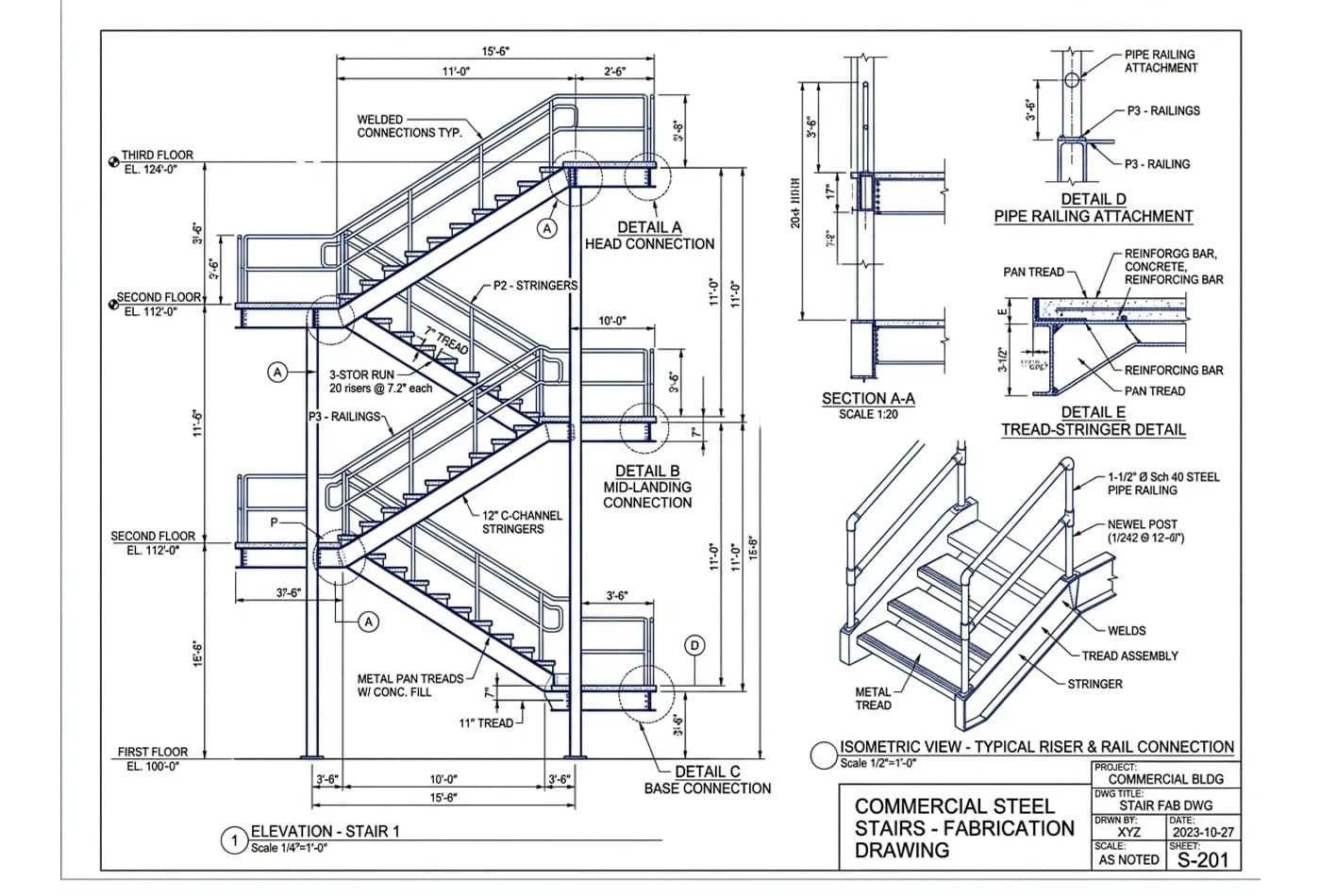
Commercial Steel Stair & Railing Fabrication
Two-story egress stair tower fabrication package showing 12" C-channel stringers, concrete-filled pan treads, 1-1/2" Schedule 40 pipe railings, newel post anchoring, mid-landing support columns, head connections, and isometric assembly details conforming to IBC Chapter 10.
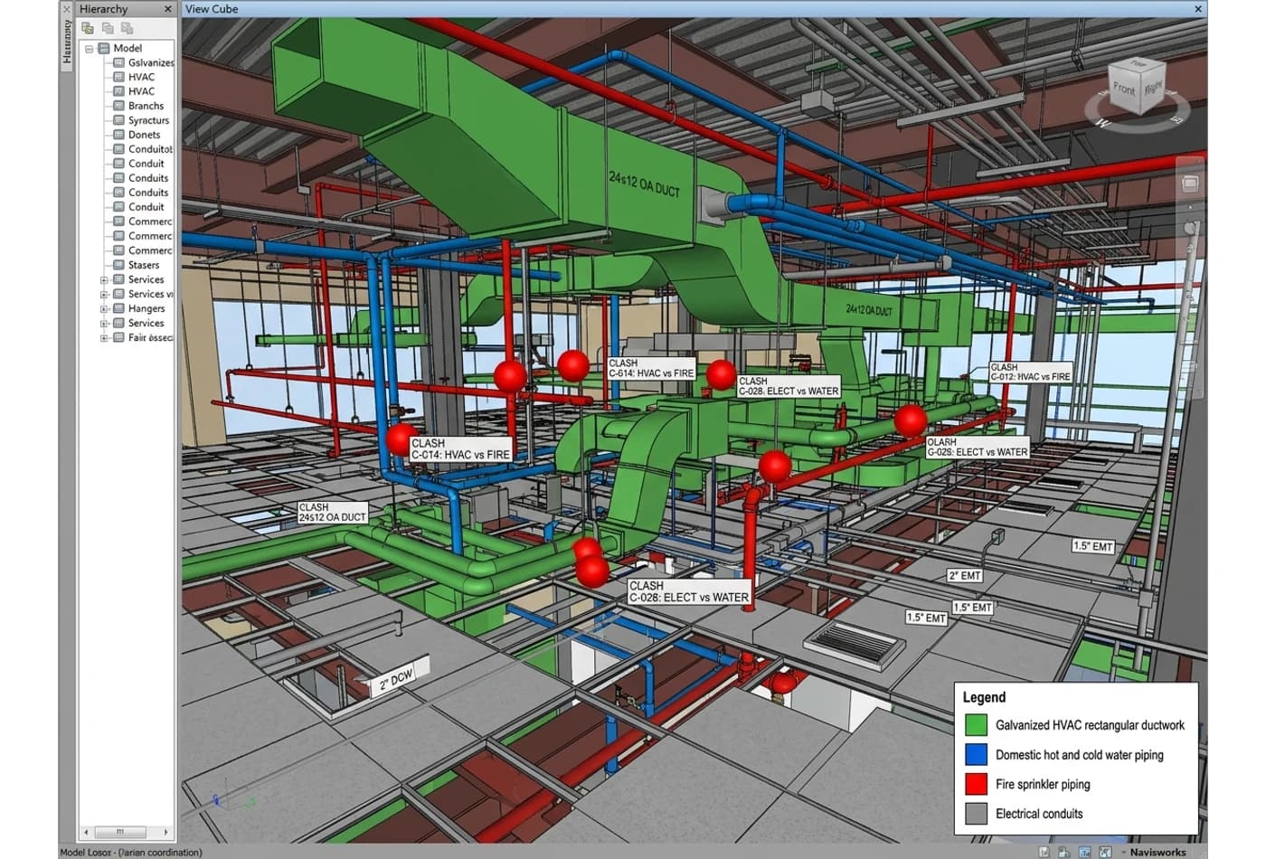
HVAC & Multi-Trade Clash Coordination Model
3D spatial coordination view identifying and resolving geometric interferences between 24x12 galvanized supply air ductwork, 2" domestic cold water piping, fire sprinkler mains, and electrical EMT conduit racks prior to ceiling grid installation.
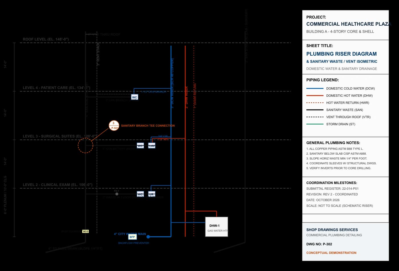
Commercial Plumbing Riser & Vent Isometric
Four-story medical office building plumbing isometric diagram. Details 4" sanitary soil stack, 3" vent through roof (VTR), 3" domestic cold water copper riser, hot water supply and recirculating return loops, base cleanout locations, and floor penetration sleeve coordinates.
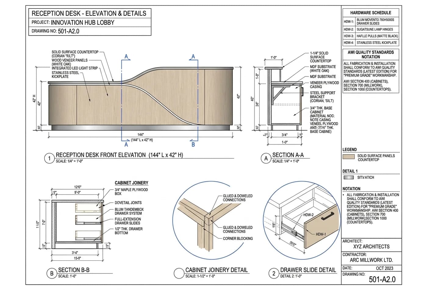
Architectural Millwork Reception Desk Details
Custom 144" commercial reception desk shop drawing. Illustrates curved solid surface countertops, white oak veneer face panels, Blum concealed drawer slides, MDF substrate framing, internal steel support brackets, wire chase cutouts, and AWI Section 400 Premium Grade compliance.
Construction Professionals We Work With
Every member of your construction team uses shop drawings differently. Here is how our documentation supports specific project roles.

General Contractors
Align subcontractor submittals into clear, coordinated drawing sets. Eliminate trade scope overlaps, prevent field change orders, and verify critical opening and embed locations before site work commences.
- Multi-trade submittal packages
- Clash detection matrices
- RFI identification logs

Project Managers
Keep projects on the critical path with phased drawing releases, documented revision turnaround cycles, and organized drawing registers tailored to CSI Section 01 33 00 submittal procedures.
- Drawing registers with delta logs
- Phase-based submission batches
- Submittal review turnaround

Site Superintendents
Receive legible field installation plans with unmistakable piece marks, clear gridline references, accurate anchor bolt patterns, and sleeve locations that match physical conditions on site.
- Erection and setting plans
- Sleeve & embed placement layouts
- Field dimension verification sheets

Estimating & Preconstruction Teams
Clarify ambiguous details during preconstruction buyout. Detect missing connection criteria or uncoordinated MEP paths early to secure firm subcontractor bids and minimize contingency risk.
- Pre-bid scope review notes
- Bill of materials (BOM) estimates
- Trade interface boundary checks

Procurement & Subcontractor Coordinators
Synchronize long-lead procurement releases for structural steel, curtain walls, and mechanical equipment with approved-for-fabrication drawing packages ready for vendor manufacturing.
- Advance bill of materials
- Cut lists & piece mark schedules
- Approved-for-fabrication releases
General Contractor Projects We Support
Drawing scope, detailing tolerances, and submittal requirements vary significantly across commercial project types. We adapt our drafting packages to match your project’s occupancy and structural classification.

Commercial Office Buildings
Mid-rise and high-rise core and shell framing, curtain wall facades, multi-tenant mechanical risers, core restroom plumbing batteries, and elevator shaft structural detailing.
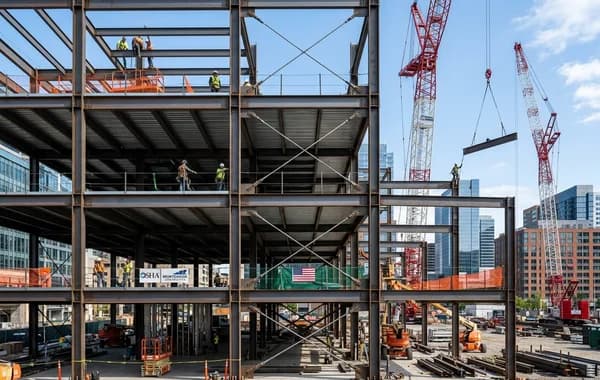
Multifamily Residential Buildings
Podium concrete construction, post-tensioned slabs, repetitive unit plumbing stacks, architectural metal balconies, egress stairs, and exterior cladding systems.
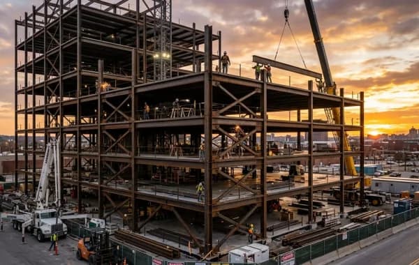
Warehouses & Distribution Facilities
Large-span structural steel joists and girders, tilt-up concrete panel reinforcement, dock leveler pit embeds, industrial roof drainage, and high-bay lighting raceways.
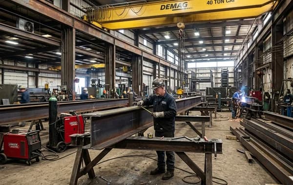
Industrial & Manufacturing Plants
Heavy equipment support steel, pipe racks, industrial platforms, mezzanines, high-pressure process piping, and overhead bridge crane runway beams.

Healthcare & Medical Facilities
Hospital surgical suites, medical gas piping distribution, radiation shielding structural frames, ceiling-mounted equipment booms, and strict vibration-isolation details.
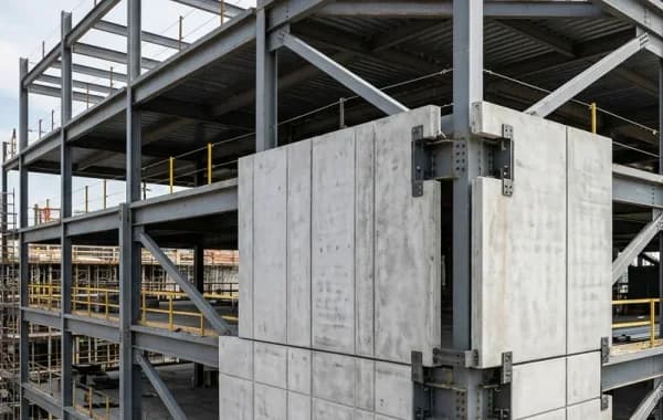
Educational & Institutional Buildings
K-12 schools, university labs, sports field houses, structural steel trusses, masonry reinforcement, high-traffic hollow metal frames, and durable architectural millwork.

Retail Developments & Shopping Centers
Open storefront framing, custom steel canopies, aluminum composite material (ACM) cladding, sign backing steel, and roof mechanical unit frames.

Renovations & Tenant Improvements (TI)
Interior commercial fit-outs, structural retrofits, new stair openings in existing slabs, custom architectural reception woodwork, and revised MEP distribution.
What General Contractors Should Send for a Shop Drawing Quote
To provide a firm price and clear timeline, we review the design documents, project specifications, and schedule parameters. Here is our recommended document checklist:
| Required Document / Information | Included Elements | Why It Affects Detailing Scope |
|---|---|---|
| Architectural Drawings (A-Sheets) | Floor plans, reflected ceiling plans (RCP), elevations, wall sections | Establishes finished dimensions, ceiling heights, and aesthetic alignments. |
| Structural Drawings (S-Sheets) | Foundation plans, framing plans, column schedules, general notes | Defines member sizes, design loads, base plate dimensions, and connection criteria. |
| MEP Drawings (M, P, E Sheets) | Duct layouts, piping risers, electrical equipment schedules | Required for spatial coordination and slab sleeve/penetration locations. |
| Project Specifications (CSI Divs) | Divisions 03 (Concrete), 05 (Metals), 06 (Wood), 08 (Openings), 22/23/26 | Specifies material grades, coatings, galvanizing, weld testing, and tolerances. |
| Addenda, Bulletins & ASIs | Architect's Supplemental Instructions, bid addenda, revision notices | Ensures quote and drawings reflect current contract documents rather than outdated sets. |
| Scope of Work Boundaries | Specific trades to detail, alternates, excluded areas, phased releases | Eliminates duplicate detailing and focuses effort strictly on contracted scope. |
| Submittal Milestones & Schedule | Critical path dates for anchor bolt release, framing, and fabrication | Allows us to sequence drafting batches to protect jobsite pour and erection dates. |
| Fabricator / Supplier Standards | Standard shop hole sizes, preferred connection details, tooling constraints | Tailors assembly drawings to the specific subcontractor’s manufacturing capability. |
| BIM Models (If Contracted) | Revit (RVT), IFC, or Navisworks (NWD) design models | Accelerates setup and enables automated clash detection in 3D. |
Managing Shop Drawing Submittals, RFIs, and Revisions
The submittal process is one of the general contractor’s primary administrative risks. A single unlogged revision, a superseded drawing distributed to the field, or an unaddressed engineer review markup can result in costly delays and backcharges.
We structure every shop drawing package to integrate directly with your submittal log and document control platform (Procore, Autodesk Construction Cloud, Bluebeam, or Submittal Exchange). Every sheet carries an unambiguous title block featuring the GC project number, trade division, submittal ID, issue purpose (e.g., For Review, For Fabrication, For Record), and a clean delta block.
Submittal Workflow Hierarchy
Note: Drafting services do not substitute for licensed engineering review. Legal approval authority remains strictly with the project Architect and Engineer of Record.
Shop Drawings vs. Design Drawings vs. As-Builts
Clear distinctions in purpose, preparer, audience, and legal authority across the primary drawing types used throughout a commercial construction project.
| Drawing Category | Primary Purpose | Typical Preparer | Primary Audience | Review & Authority |
|---|---|---|---|---|
| Design / Contract Drawings | Illustrates architectural aesthetic and structural design intent. | Architect of Record (AOR), Structural Engineer (EOR), MEP Engineers | General contractor, estimators, municipal building officials | Stamped and sealed by licensed design professionals for permit. |
| Shop Drawings (Our Core Focus) | Provides exact fabrication, cutting, assembly, and field installation dimensions. | Professional detailing and drafting service / trade fabricator | Shop fabricators, field ironworkers, carpenters, plumbers, electricians | Reviewed by GC, then submitted to AOR/EOR for design conformance review. |
| Coordination Drawings | Resolves spatial interferences between trades before fabrication begins. | GC / BIM coordinator / multi-trade detailing provider | Trade foremen, project engineers, site superintendents | Reviewed internally by GC and trade subcontractors during sign-off meetings. |
| Record / As-Built Drawings | Documents final physical installation, field modifications, and RFI changes. | General contractor from field redlines / drafting provider conversion | Building owner, facility operations, future renovation teams | Submitted to owner at closeout as contractual record of completed work. |
Common Shop Drawing Issues That Can Delay Construction
Field rework on commercial construction sites is ten to twenty times more expensive than resolving discrepancies during the detailing phase. Here is how rigorous shop drawings prevent common jobsite delays:
Discrepancies Between Arch & Struct Plans
When architectural column centerlines differ by inches from structural gridlines, framing fabricated off design drawings fails on site. Our initial scope setup audits grids to reconcile discrepancies via early RFIs.
Ducts Colliding with Beam Flanges
Large supply ductwork requiring 24\" depth running beneath beams with only 14\" clearance. 3D spatial modeling discovers clashes virtually, prompting beam penetration sleeves or rerouting before duct manufacture.
Forgotten Concrete Inserts & Anchor Rods
Stairs or canopy steel needing connection to concrete walls where embeds were never poured. We produce coordinated embed placement plans released in advance of concrete pours.
Core Drilling Post-Tensioned Slabs
Drilling plumbing penetrations through post-tensioned cables risks catastrophic structural failure. Our sleeve layout drawings pinpoint penetration coordinates before PT tendons and rebar are placed.
Jobsite Using Superseded Plans
Fabricating steel or cutting millwork based on pre-addenda drawings. Every reissued sheet has prominent delta revision bubbles and updated revision dates, eliminating version confusion.
Scope Gaps Between Subcontractors
Ambiguity over whether the steel fabricator or mechanical contractor supplies rooftop equipment dunnage. Our scope boundary reviews highlight interface points to ensure total buyout coverage.
Quality Checks Before Shop Drawing Submission
Every drawing package undergoes internal multi-stage quality control checks before transmittal to the general contractor, ensuring submittals are constructible, complete, and formatted for rapid engineer review:

Drawing Completeness
Verification that all members, plates, fasteners, weld symbols, and dimensions called for in the contract documents are represented on the sheet.

Dimension Coordination
Cross-checking mathematical string dimensions against overall building gridlines to eliminate cumulative measurement discrepancies.

Model & 2D Consistency
Validating that 2D section cuts, elevations, and details align seamlessly with the underlying 3D BIM or Tekla structural model.
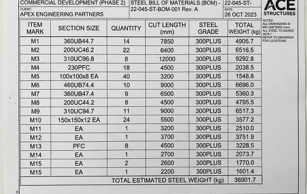
Material & Specification Match
Cross-referencing ASTM material callouts, bolt grades, rebar yields, and finish requirements against the project specification divisions.
Piece Mark Uniqueness
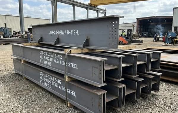
Ensuring that every fabricated assembly, bar mark, and detail callout carries a unique, non-duplicative designation matching the erection plan.
Revision Cloud Audit
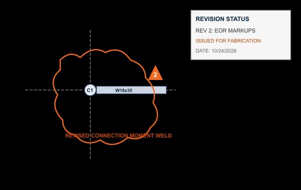
Confirming that on revised issues, all modified elements are enclosed in revision clouds with matching delta symbols in the title block.
Scope Inclusions Verification
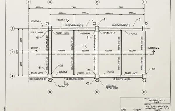
Ensuring that contracted scope boundaries, base contract requirements, and approved change orders are fully detailed without gaps.

Transmittal Documentation
Formatting final drawing registers, transmittal covers, and vector PDF sets to match the GC’s document management upload protocols.
Drawing Deliverables and Coordination Formats
We deliver outputs formatted to integrate directly with your project document control workflows and subcontractor fabrication equipment.
Vector PDF Drawing Sets
Full-size architectural sheets (Arch D 24x36, Arch E 36x48) with searchable text, clean line weights, and hyperlinked sheet callouts for Bluebeam review.
Native CAD (DWG / DXF)
Organized layer-managed AutoCAD DWG files ready for contractor background overlays, site layout surveying, and field laser coordination.
3D BIM Models (IFC / RVT)
Intelligent 3D geometry in open standard IFC 2x3/4 and native Autodesk Revit formats for multi-trade federation and spatial coordination.
BOM & CNC Data (XLSX / DSTV)
Detailed Bills of Materials, bar bending schedules, and automated DSTV/NC1 files for automated steel beam drills and plate plasma cutters.
Software Systems Utilized for Detailing & Coordination






What Affects Shop Drawing Cost and Turnaround?
Unlike cookie-cutter drafting services with misleading fixed-rate claims, shop drawing effort on commercial projects depends on measurable technical criteria. Here are the primary drivers of drafting effort and schedule:
Building Size & Repetition
Total gross square footage and the degree of structural/architectural repetition. Repetitive typical floors reduce detailing hours compared to custom non-linear geometry.
Number of Trades Included
Single-trade packages (e.g., structural steel only) require fewer coordination hours than combined multi-trade packages requiring spatial inter-trade clash resolution.
Design Document Completeness
Projects with 100% Issued for Construction (IFC) plans require far fewer RFI cycles and turnaround days than schematic 50% design-build or fast-tracked bid sets.
BIM Modeling Requirements
Contract specifications mandating 3D LOD 400 fabrication models and federated clash reporting require additional modeling and coordination meetings compared to 2D CAD.
Phased Submittal Sequences
Batching submittals into milestone releases (e.g., Phase 1 Foundations & Anchor Bolts, Phase 2 Tier 1 Steel) requires structured project management alignment.
Revision & Change Order Volume
Substantial post-award design bulletins or architectural floor plan adjustments require systematic delta tracking and re-submittal management.
Need a Detailed Shop Drawing Proposal for an Upcoming Bid?
Share your architectural and structural drawings for a transparent, fixed-scope proposal.
Typical Scope Inclusions and Standard Exclusions
To ensure clear contractual boundaries and prevent scope gaps during subcontractor buyout, here is our standard scope delineation:
Typical Included Work
- Preparation of detailed shop fabrication and assembly drawings based on contract documents.
- General arrangement plans, anchor bolt setting plans, and erection layout drawings.
- Member piece marking, cut lengths, weld symbols, and bolt spacing to project specifications.
- Detailed Bills of Materials (BOM), takeoffs, and bar bending schedules (BBS).
- Identification of dimension discrepancies and drafting of formal RFI clarification sketches.
- Incorporation of standard Architect and Engineer of Record review markups with delta tracking.
- Delivery of vector PDFs, DWG native CAD files, and CNC automated fabrication data (DSTV/NC1).
Standard Exclusions (Unless Contracted Separately)
- Original structural engineering design, building load calculations, and member sizing.
- Official legal Engineer of Record (EOR) submittal approval stamps.
- Professional Engineering (PE/SE) calculations (available only via delegated connection design agreements).
- Municipal building permit applications, permit fees, and regulatory hearings.
- On-site physical surveying, physical layout verification, and field welding inspections.
- Jobsite safety planning, fall protection engineering, and OSHA site supervision.
- Contractor means, methods, hoisting techniques, crane staging, and erection sequences.
Frequently Asked Questions About Shop Drawing Services for General Contractors
Clear answers to the common operational, technical, and submittal questions general contractors ask when evaluating outsourced drafting support.
Need Shop Drawings for Your General Contracting Project?
Send us your architectural and structural plans for a detailed scope review and quotation. Our team coordinates across trades to eliminate field clashes, streamline your submittal log, and support your construction schedule.