
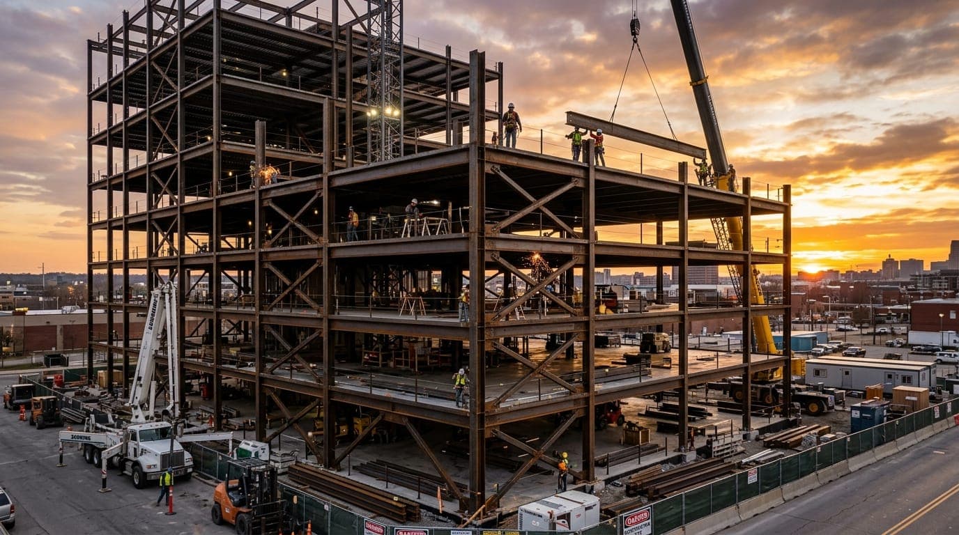
Structural Steel Shop Drawings & Detailing Services
Accurate, fabrication-ready structural steel shop drawings for American steel fabricators, general contractors, and trade subcontractors. We deliver buildable member assembly sheets, erection plans, connection details, and bills of materials that keep construction schedules on track and within budget.
Milestone Turnarounds
Phased submittals ready in 3–7 business days to support foundation pours and shop fabrication milestones.
Full Digital Deliverables
Vector PDF, native DWG, 3D IFC models, Tekla exports, and CNC DSTV files for automated saws and drills.
Buildable & Coordinated
Complete member assemblies, connection cuts, and anchor bolt layouts cross-checked for field fit-up.
RFI & Submittal Support
Active RFI resolution, prompt engineering markup incorporation, and strict title block revision tracking.
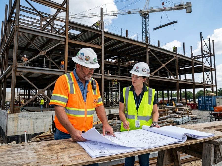
Accurate Steel Shop Drawings for Fabrication and Erection
Structural steel shop drawings are comprehensive, fabrication-ready engineering documents that translate structural design drawings and architectural plans into exact, constructible components. In commercial steel construction, shop drawings serve as the vital technical bridge between design intent and physical fabrication, providing the precise geometry, hole spacing, weld symbols, and cut lengths required to manufacture every beam, column, brace, and connection plate.
In the fabrication shop, detailed drawings guide saw operators, drill lines, fitters, and certified welders, ensuring that structural members match AISC dimensional tolerances. In the field, coordinated steel erection plans provide ironworkers and crane operators with sequential framing marks, gridline references, bolt schedules, and shake-out layouts to ensure safe, efficient hoisting and alignment without jobsite clashes.
Our detailing process involves rigorous cross-referencing between architectural elevations, structural general notes, foundation anchor bolt setting plans, and mechanical penetrations. When dimension discrepancies or connection ambiguities arise, we formulate clear, structured Requests for Information (RFIs) to resolve issues before raw steel is ordered or cut.
Engineering Responsibility & Design Boundary:
ShopDrawingServices.us prepares precision fabrication shop drawings and erection plans derived from authorized contract documents. The preparation of shop drawings does not independently replace structural engineering design, code compliance certification, or formal submittal review. Professional engineering stamps (PE/SE) and connection design calculations remain under the legal jurisdiction of the project Engineer of Record (EOR) or designated licensed specialty connection engineer.
Our Structural Steel Detailing Capabilities
We detail commercial, industrial, and institutional structural steel framing packages adhering to current AISC standards, project specifications, and fabricator shop equipment requirements.
Beam and Column Detailing
Comprehensive fabrication assembly sheets and single-part drawings for wide-flange beams (W-shapes), structural columns, hollow structural sections (HSS), structural tees, channels, and angles. Drawings document exact member piece marks, cut-to-fit lengths, hole centerlines, bolt gauges, web copes, flange bevels, stiffener locations, and specified camber profiles derived directly from contract framing plans.
- Column schedules with splice elevations & cap plate details
- Beam coping, web penetrations & mechanical clearance coordination
Bracing and Truss Detailing
Accurate detailing for vertical cross-bracing, chevron (inverted-V) bracing, eccentric braced frames (EBF), and long-span roof trusses. We detail top and bottom chords, web diagonals, work-point coordinates, and heavy gusset plates with complete weld callouts, edge distance compliance, and field splice arrangements for constructible site assembly.
- Work-point verification and gusset plate layout geometry
- Shop-welded and field-bolted truss transport assemblies
Steel Connection Documentation
Full detailing of shop-welded and field-bolted connections following design engineer reaction schedules or delegated connection design tables. We document single-plate shear tabs, double clip angles, shear end plates, seated connections, and moment-resisting connections (flange-plated, directly welded, or bolted extended end-plates) with proper bolt spacing and tool clearances.
- Compliance with AISC 360 and RCSC structural joint standards
- Standard, short-slot, and oversized bolt hole callouts
Base Plates and Anchor Rod Layouts
Essential setting plans that bridge structural steel with cast-in-place concrete foundations. We detail column base plate dimensions, hole diameters, hole patterns, leveling plate details, grout pocket allowances, anchor rod diameters, embedment depths, projection heights, hook orientations, and template fabrication sheets for accurate jobsite placement.
- Direct cross-referencing with foundation engineering drawings
- AISC Design Guide 1 column base plate clearance standards
Steel Erection Documentation
Framing plans, 3D general arrangement layouts, column grid references, and sequential erection markups developed specifically for ironworkers. Plans show member piece marks matching shop tags, field connection marks, field bolt schedules (quantity, diameter, length), temporary bracing provisions, lifting lug locations, and shake-out delivery staging.
- Grid-correlated member marks matching shop tags
- Field weld callouts, torque notes & safety cable attachments
Steel Material Lists & BOMs
Structured bills of materials, advance procurement bills, cutting lists, and hardware summaries generated directly from the 3D detailing model. Reports detail member quantities, steel grades (e.g., ASTM A992, A36, A500 Grade B/C), linear cut lengths, plate nesting dimensions, calculated weights, and surface preparation specifications (primer, galvanizing, or fireproofing).
- Advance ordering bills to expedite mill steel procurement
- Export formats compatible with FabSuite, FabTrol, and Excel
Structural Steel Shop Drawings vs Erection Drawings
In structural steel construction, clarity between shop fabrication and field erection is essential for project success. While both drawing sets originate from the coordinated 3D structural model, they serve distinct audiences, convey different levels of detail, and fulfill separate functions under standard AISC project delivery workflows.
| Feature / Scope | Shop Fabrication Drawings | Steel Erection Drawings |
|---|---|---|
| Main Purpose | Provide exact manufacturing instructions to cut, drill, fit, and weld individual steel members and sub-assemblies in the fabrication facility. | Guide ironworkers, crane operators, and site superintendents on hoisting, placing, aligning, and bolting the steel frame on the jobsite. |
| Primary Audience | Steel fabricators, shop fitters, certified shop welders, machine operators, and automated CNC saw/drill line programmers. | Field steel erectors, ironworkers, crane riggers, general contractor field superintendents, and building structural inspectors. |
| Drawing Content | Single-part sheets, assembly sheets, cut lengths, cope geometry, web bevels, hole gauges, welding symbols (AWS), and surface prep notes. | Overall framing plans, column grid references, building elevations, section cuts, field bolt schedules, anchor rod plans, and shake-out staging. |
| Member Identification | Detailed piece marks (e.g., 1B1, 2C4) with individual fitting part marks (e.g., p1, a1, b1) identifying every clip, plate, and stiffener. | Shipping piece marks (e.g., 1B1, 2C4) correlated to specific column grid lines, floor elevations, and framing levels. |
| Dimensions & Tolerances | Absolute member fabrication dimensions down to 1/16-inch tolerances per AISC 303 Code of Standard Practice Section 6. | Grid-to-grid spacing, column centerline offsets, finished floor elevations (T.O.S., T.O.B.), and building plumb line tolerances. |
| Fabrication Instructions | Explicit cutting, hole punching, drilling, welding, grinding, cambering, and shop priming/galvanizing instructions. | Field bolt types (snug-tight vs. pretensioned), torque requirements, field welding callouts, temporary bracing, and safety cable attachments. |
| Review & Coordination Needs | Reviewed by fabricator QA, submitted through general contractor to Engineer of Record (EOR) for design compliance sign-off. | Reviewed by GC, erector, EOR, and municipal building inspectors to ensure site safety, structural stability, and code compliance. |
* Note: Exact drawing requirements, deliverable formats, and submittal review workflows depend on the governing contract documents, project specifications, and local jurisdiction building requirements.
What's Included in Our Structural Steel Shop Drawings
Every drawing package is prepared to national US detailing conventions, clearly organized into logical submittal sets for seamless shop production and site erection.
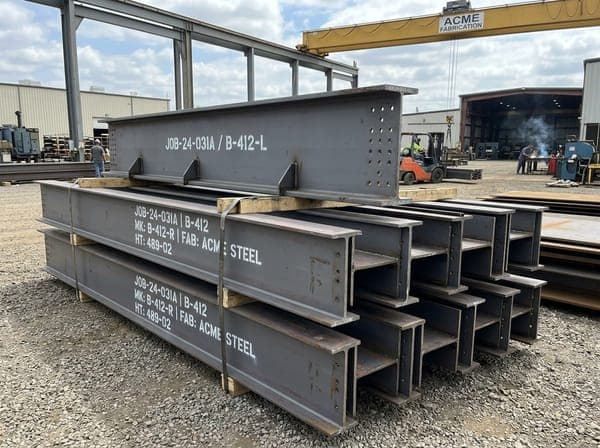
Shop Fabrication Drawings
Detailed member, plate, and assembly drawings with exact dimensions, weld callouts, hole spacing, and piece marks for shop production.
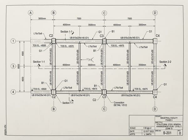
General Arrangement Drawings
Overall building framing plans, member locations, gridline references, elevations, and section cuts coordinating full structural geometry.
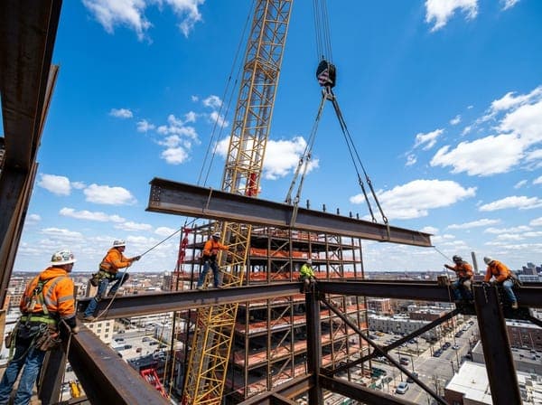
Steel Erection Plans
Sequential erection plans, grid references, field bolt callouts, shake-out lists, and installation details for field ironworkers.
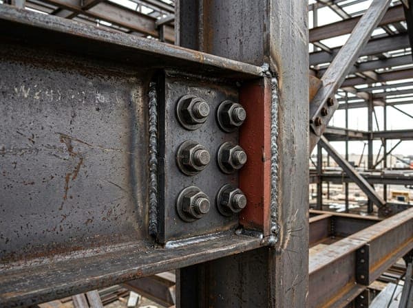
Connection Details
Shear tabs, moment connections, bracing gussets, and splices detailed to approved project criteria and standard AISC guidelines.
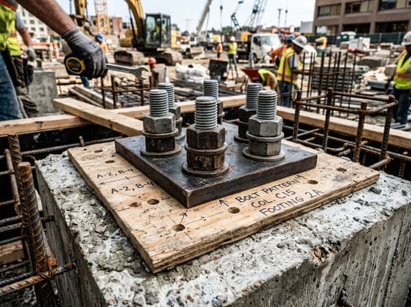
Anchor Bolt & Embed Plans
Anchor rod setting layouts, column base plate templates, embedment depths, leveling details, and foundation coordination.
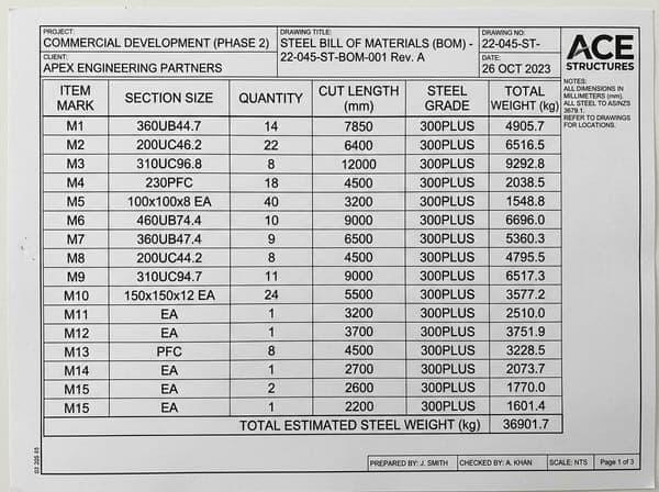
Bill of Materials (BOMs)
Comprehensive material takeoffs, advance bills, cutting lists, fastener summaries, and tonnage calculations ready for procurement.
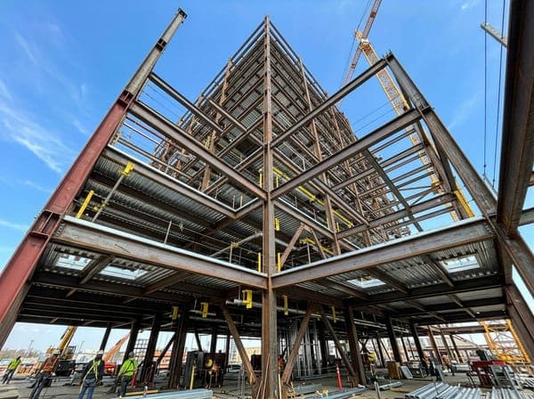
RFIs & Coordination
Formal Requests for Information (RFIs) with sketch attachments to clarify dimension clashes, drawing ambiguities, and scope conflicts.
Custom Deliverable Configurations: Final submittal deliverables depend upon individual project specifications, fabricator shop equipment, and contractual agreements. Advanced BIM exports (.ifc, .rvt), CNC DSTV files, and custom material management data can be tailored to your production workflow upon scope confirmation.
Documents Required for Structural Steel Detailing
Starting detailing with a complete, current, and coordinated document set prevents out-of-sequence detailing, minimizes RFIs, and ensures fabrication drawings align with the latest design revisions.
Design & Engineering Documents
- Structural Engineering Drawings: Complete set including general notes, framing plans, sections, and column schedules.
- Architectural Drawings: Floor plans, exterior wall sections, roof plans, and finished floor elevations for edge clearances.
- Project Specifications: Division 01 (General Requirements) and Division 05 (Metals / Structural Steel) specifications.
- Connection Design Criteria: Standard reaction tables, moment criteria, or delegated connection engineering calculations.
- Addenda & Revisions: All current addenda, architectural/structural bulletins, and responses to pre-bid RFIs.
Fabrication Preferences & Schedule
- Fabricator Shop Standards: Preferred hole sizes, bolt diameters, standard clip angle profiles, and maximum shipping lengths.
- Paint & Finish Requirements: Shop primer specifications, surface prep standards (e.g., SSPC-SP 6), or galvanizing notes.
- CNC Machine Requirements: DSTV file format specifications for automated CNC saw, drill, and plate machinery.
- Project Phasing Schedule: Phased release sequences (e.g., anchor bolts first, Tier 1 columns, Tier 2 beams) and milestone dates.
- CAD & BIM Reference Files: Native 2D DWG files or 3D Revit models (.rvt/.ifc) where available to expedite setup.
Steel Connection Detailing and Fabrication Coordination
Connection detailing is one of the most critical phases in structural steel detailing. Structural joints must safely transfer design loads while accommodating practical fabrication tool clearances, erection fit-up tolerances, and cost-effective assembly methods. Our detailing team prepares comprehensive connection documentation in strict accordance with project contract criteria and standard AISC Manual conventions.
We detail high-strength bolted connections complying with the Research Council on Structural Connections (RCSC) Specification, identifying snug-tight, pretensioned, and slip-critical joints with standard, short-slotted, or oversized holes. Welded joints are detailed using American Welding Society (AWS D1.1) prequalified welding symbols, clearly indicating fillet weld sizes, partial-joint-penetration (PJP), and complete-joint-penetration (CJP) groove welds with backing bars and weld-access holes.
From shear tabs and double-angle beam connections to heavy column base plates, moment-resisting end plates, and vertical bracing gussets, we verify that every bolt and weld is accessible for shop tools and field spud wrenches. When connection reactions exceed standard tables or geometric interferences occur, we issue formal Requests for Information (RFIs) with clear 3D sketches to secure timely direction from the Engineer of Record.
Connection Types Detailed
Structural Steel Detailing Standards and Review Requirements
Our detailing methodologies align with nationally recognized steel design, detailing, bolting, and welding standards established across the American construction industry.
ANSI/AISC 303
The foundational code defining the contractual relationship between steel fabricator, detailer, and Engineer of Record. Governs drawing submittal workflows, approval timelines, release for construction protocols, fabrication tolerances, and erection clearances.
ANSI/AISC 360
Specification for Structural Steel Buildings. While a design specification for structural engineers rather than a detailing checklist, it defines member limit states, material grades (ASTM A992/A36), and connection criteria that shop drawings must accurately reflect.
RCSC Specification
Governs structural joints using high-strength bolts (ASTM F3125 Grades A325 and A490). We detail bolt spacing, edge distances, and hole clearances for snug-tight, pretensioned, and slip-critical joints with correct washer callouts.
AWS D1.1 / D1.1M
The American Welding Society standard for structural steel welding. Governs standard welding symbols, prequalified joint details, effective weld sizes, filler metal callouts, backing bar details, and shop inspection access.
What Your Structural Steel Drawing Package May Include
We structure our drawing packages to provide complete technical clarity across both shop fabrication and field erection workflows.
| Deliverable | Typical Information Included | Project Purpose |
|---|---|---|
| Shop Fabrication Drawings | Assembly sheets, single-part details, member piece marks, cut lengths, hole centerlines, bolt gauges, weld symbols (AWS), cope cuts, bevel details, surface prep, and shipping tags. | Shop cutting, fitting, drilling, welding, and QA inspection. |
| Steel Erection Plans (GA) | Framing layout plans, grid lines, column mark locations, elevations, section cuts, field bolt callouts, shake-out lists, and installation sequencing notes. | Field hoisting, positioning, alignment, and site bolting. |
| Connection Detail Sheets | Detailed cuts of shear tabs, clip angles, moment connections, bracing gussets, column splices, and stiffener plates with complete bolt gauges and weld callouts. | Fabrication fit-up and EOR submittal review compliance. |
| Anchor Rod & Foundation Setting Plans | Anchor rod layouts, center-to-center dimensions, projection heights, embedment depths, base plate orientations, leveling plate details, and grout tolerances. | Concrete foundation pre-pour setting and inspection. |
| Bills of Materials & Cut Lists (BOM) | Itemized lists of member piece marks, section profiles, steel grades (e.g., A992, A36, A500), cut lengths, calculated weights, and bolt takeoffs. | Steel procurement, inventory nesting, and shipping logistics. |
| Drawing Revisions & RFI Log | Numbered revision clouds, delta title block entries, description of changes, date stamps, and cross-referenced formal RFI responses. | Version control and contractual design change tracking. |
Who We Work With in the Steel Industry
Our structural steel shop drawings support a wide range of project stakeholders across commercial, industrial, and institutional construction.

Steel Fabricators
Shop-ready assembly sheets, piece mark details, and CNC DSTV files to streamline cutting, drilling, and shop fitting.

General Contractors
Clash-coordinated framing packages, accurate anchor rod layouts, and clear submittals that keep schedules on track.
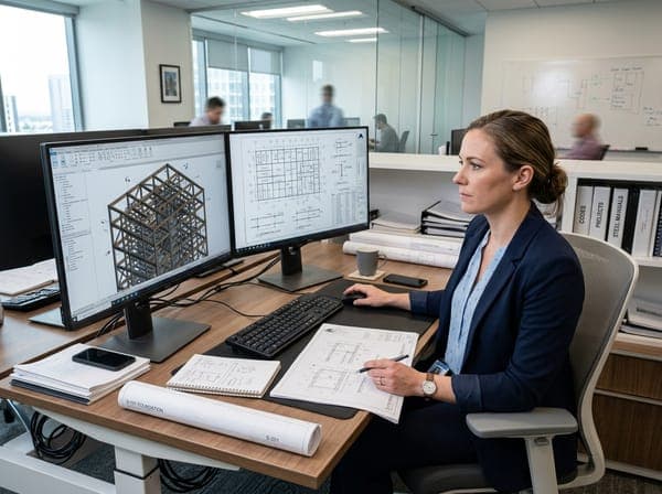
Structural Engineers
Drawings faithfully translating design intent into constructible geometry with disciplined RFI tracking and submittal clarity.
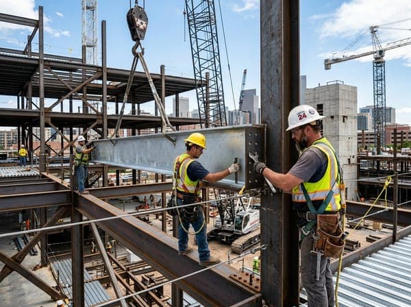
Steel Erectors
Sequential erection drawings, unambiguous field bolt marks, and clear section cuts for safe, efficient jobsite hoisting.
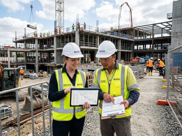
Project Managers
Predictable phased submittal milestones, fast revision turnarounds, and reliable documentation for contract compliance.
A Disciplined 4-Step Detailing Workflow
From contract drawings to released-for-construction shop packages, we maintain disciplined quality control and transparent communication throughout each project milestone.
Project Review & Scope Setup
We review structural drawings, architectural plans, specifications, addenda, and connection design criteria. Missing dimensions and conflicts are identified early to generate initial RFIs.
3D Modeling & Detailing
Using Tekla Structures and AutoCAD, our detailers build an intelligent 3D structural model. We generate anchor bolt setting plans, member assembly drawings, single-part sheets, and bills of materials.
Coordination & Review Cycle
Submittal drawing sets are coordinated with fabricator standards and transmitted to the general contractor and EOR for review. Markups and revision comments are incorporated with clear revision clouds.
Final Shop Release Delivery
Approved drawings are released for fabrication with complete vector PDF sets, native DWG files, 3D IFC models, cutting lists, and CNC DSTV files for automated shop lines.
Common Steel Detailing Issues We Help Identify
Building a coordinated 3D structural model uncovers dimensional conflicts and drawing omissions early—allowing the team to resolve discrepancies before steel is cut or delivered to the site.
Missing or Conflicting Centerline Dimensions
Structural and architectural drawings frequently exhibit slight dimension discrepancies across gridlines. Our modeling process flags discrepancies immediately, allowing RFIs to confirm true grid dimensions before fabrication begins.
Inconsistent Top-of-Steel (T.O.S.) Elevations
Differences between architectural floor finishes and structural beam elevations can cause costly concrete slab or deck thickness errors. We cross-reference all section cuts to establish verified top-of-steel datums.
Unclear Connection Design Criteria
Contract drawings sometimes omit specific beam end reactions or connection details for skewed framing. We identify missing criteria early and request EOR reaction schedules to ensure connections are appropriately sized.
Anchor Rod and Foundation Interferences
Column base plates placed adjacent to grade beams, slab depressions, or foundation walls can cause anchor rod edge-distance conflicts. We coordinate anchor patterns with foundation geometry to prevent field drilling.
Structural vs. Architectural Cladding Discrepancies
Curtain wall anchors, precast panel embeds, and masonry relief angles must interface precisely with perimeter spandrel beams. We verify exterior envelope clearances and embed plate locations to ensure seamless trade coordination.
Incomplete Framing at Openings & Penetrations
Stairwell openings, elevator hoistways, and large mechanical duct shafts require coordinated header and trimmer framing. We verify shaft dimensions against architectural core plans to incorporate required opening steel.
Missing Fabrication & Surface Finish Specifications
Omitted paint boundaries—such as areas requiring masked contact surfaces for slip-critical joints or unpainted steel scheduled for intumescent fireproofing—are clarified so fabricators prepare surfaces correctly.
Out-of-Sequence Revision Conflicts
When design addenda arrive during active shop fabrication, tracking revisions across multiple sheets is crucial. We isolate affected piece marks with delta clouds so unaffected members continue through shop production without pause.
* Note: While detailed drafting and 3D modeling significantly reduce field clashes, project coordination is an iterative process requiring ongoing collaboration among the detailer, fabricator, general contractor, and Engineer of Record.
Structural Steel Shop Drawing Examples
Explore sample drawing deliverables from our typical project packages. Deliverables are organized, accurately annotated, and prepared for fabrication.
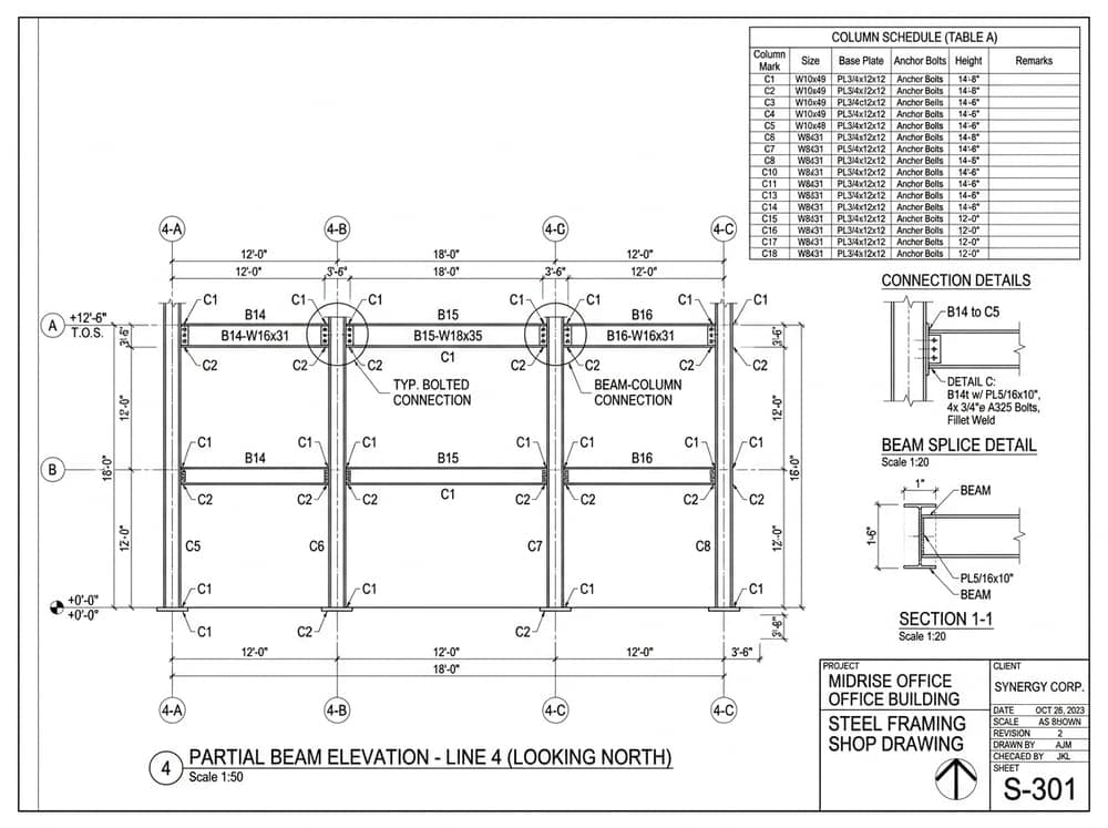 Sheet S-301
Steel Framing Shop Drawing
Detailed beam-and-column fabrication assembly sheet showing member elevations, cut lengths, welding callouts, cope profiles, and piece marks.
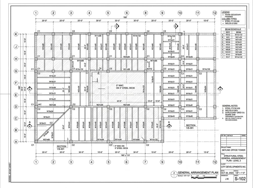 Sheet S-102
General Arrangement Drawing
Overall building steel layout displaying structural column grids, framing elevations, member marks, matchlines, and connection callouts.
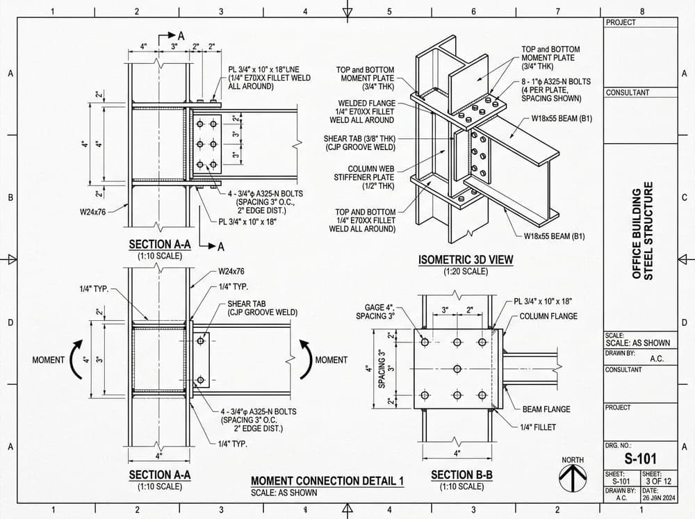 Sheet S-101
Connection Detail Drawing
High-load moment connection and shear tab detail showing bolt gauges, edge distances, weld sizes, stiffener plates, and gusset geometry.
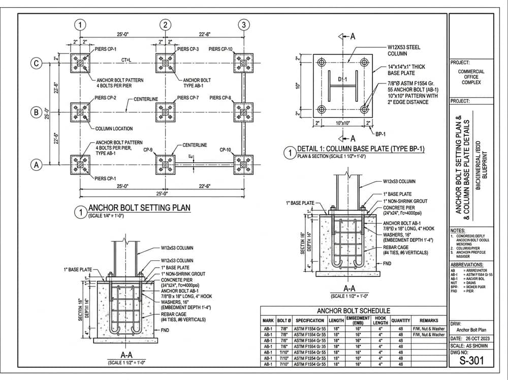 Sheet S-301
Anchor Bolt Plan
Comprehensive anchor bolt layout with center-to-center dimensions, bolt projection heights, embedment depths, base plate orientation, and grout tolerances.
Production Software & Modeling Tools
We utilize verified industry-standard software to deliver high-quality, accurate, and compatible drawings.




What Affects Structural Steel Detailing Costs?
Every construction project has unique structural demands. We provide transparent, itemized fixed-fee quotations based on actual drawing scope, avoiding hidden charges or unexpected extras.
1. Total Structural Tonnage
Overall steel weight provides an initial baseline for detailing scope, member count, and material list generation.
2. Assembly Repetition
Highly repetitive bay framing requires fewer unique shop sheets than complex facilities with distinct custom members.
3. Connection Complexity
Standard shear connections cost less to detail than complex moment frames, heavy bracing gussets, or seismic connections.
4. Structural Geometry
Orthogonal framing grids are straightforward; skewed walls, curved beams, and irregular canopies require additional modeling time.
5. Drawing Completeness
Complete engineering drawings with clear reaction tables minimize RFIs, keeping detailing production smooth and cost-effective.
6. Fabricator Standards
Incorporating specialized shop standards, custom title blocks, or proprietary clip profiles is factored into project setup.
7. Deliverable Requirements
Standard 2D PDF/DWG packages differ from multi-format scopes requiring CNC DSTV files, 3D IFC models, and advance BOMs.
8. Turnaround Schedule
Standard scheduled milestone delivery versus urgent, expedited submittals to meet tight mill procurement dates.
Rigorous Quality Control for Steel Shop Drawings
We combine technical detailing experience with disciplined multi-stage drawing review to deliver constructible, error-free drawing packages.
Accurate & Buildable Drawings
Minimize field clashes and expensive jobsite rework through rigorous dimensional cross-checks and 3D geometric validation.
US Standards Knowledge
Drafting workflows aligned with AISC, RCSC, and AWS specifications for commercial, industrial, and institutional construction.
Milestone-Driven Turnaround
Structured phased delivery schedules designed to support fabricator purchasing lead times and jobsite erection milestones.
Active Submittal Support
Dedicated coordination throughout submittal review, managing prompt RFI resolutions, markup clouds, and revision tracking.
Internal 4-Stage Drawing Review Checklist
Structural Steel Shop Drawings – FAQs
Find clear, technical answers to common questions about our structural steel shop drawings, submittal workflows, connection detailing, and turnaround milestones.
Get Accurate Structural Steel Shop Drawings for Your Project
Submit your structural and architectural drawings today for an itemized, fixed-fee quotation. Our detailing team is ready to support your fabrication schedule with accurate, constructible shop drawings.