The short answer: three sets, three jobs
On a structural steel job, three drawing sets move between the office, the shop, and the field. They look similar, they share the same piece marks, and they are often confused with each other. That confusion is expensive. A shop drawing sent to the field crew will slow them down with fabrication detail they do not need. An erection drawing sent to the shop will leave the fabricator guessing about cuts, holes, and welds. A fabrication drawing treated as an approval drawing will stall the submittal process, because it was never meant for the engineer of record.
Here is the distinction in one paragraph. Shop drawings are the detailed, approval-ready drawings that show how each member and connection will be built, and they are submitted to the engineer for review. Fabrication drawings are the shop floor working set, cut from the approved model, that tells the shop exactly how to cut, drill, weld, and finish every piece. Erection drawings are the field set that tells the erector where every piece goes, in what sequence, and with what field connections. Same steel, three audiences, three purposes.
This guide explains what each set contains, who approves it, and the five mix-ups that most often cause rework on US steel jobs. If you are a general contractor, fabricator, or erector deciding what to ask your detailer for, start with the comparison table in the middle of this article, then use the checklist at the end before you release anything to the shop or the field.
What a shop drawing actually is
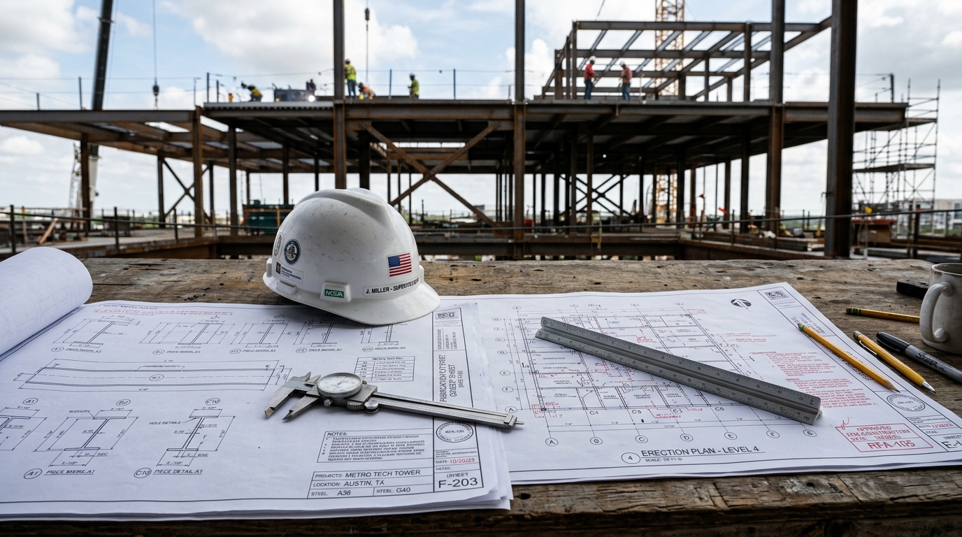
A shop drawing is the detailer's interpretation of the design documents, developed to a level the fabricator can build from. The structural engineer's drawings show member sizes, design loads, and connection intent. They do not show every bolt hole, weld length, cope, and camber the shop needs. The shop drawing fills that gap. It shows each member with its dimensions, material grade, finish, connection details, and piece mark, plus the assembly details that tie members together.
Under the AISC Code of Standard Practice for Steel Buildings and Bridges (AISC 303), shop drawings are approval drawings. That is the key legal and procedural fact. They are submitted to the engineer of record, reviewed, and returned with an approval stamp before fabrication begins. The approval process exists because the detailer makes hundreds of small decisions that the design drawings leave open: exact bolt layouts, weld sizes within the design criteria, plate thicknesses, and erection clearances. The engineer checks those decisions against the design intent, and the approval stamp is the record that the check happened.
A complete shop drawing package for a steel job typically includes anchor bolt and embed plans, framing plans, member detail sheets, connection details, and a bill of materials. Our structural steel submittal checklist walks through what the engineer checks on first review, and the seven reasons packages get returned.
Fabrication drawings: the shop floor set
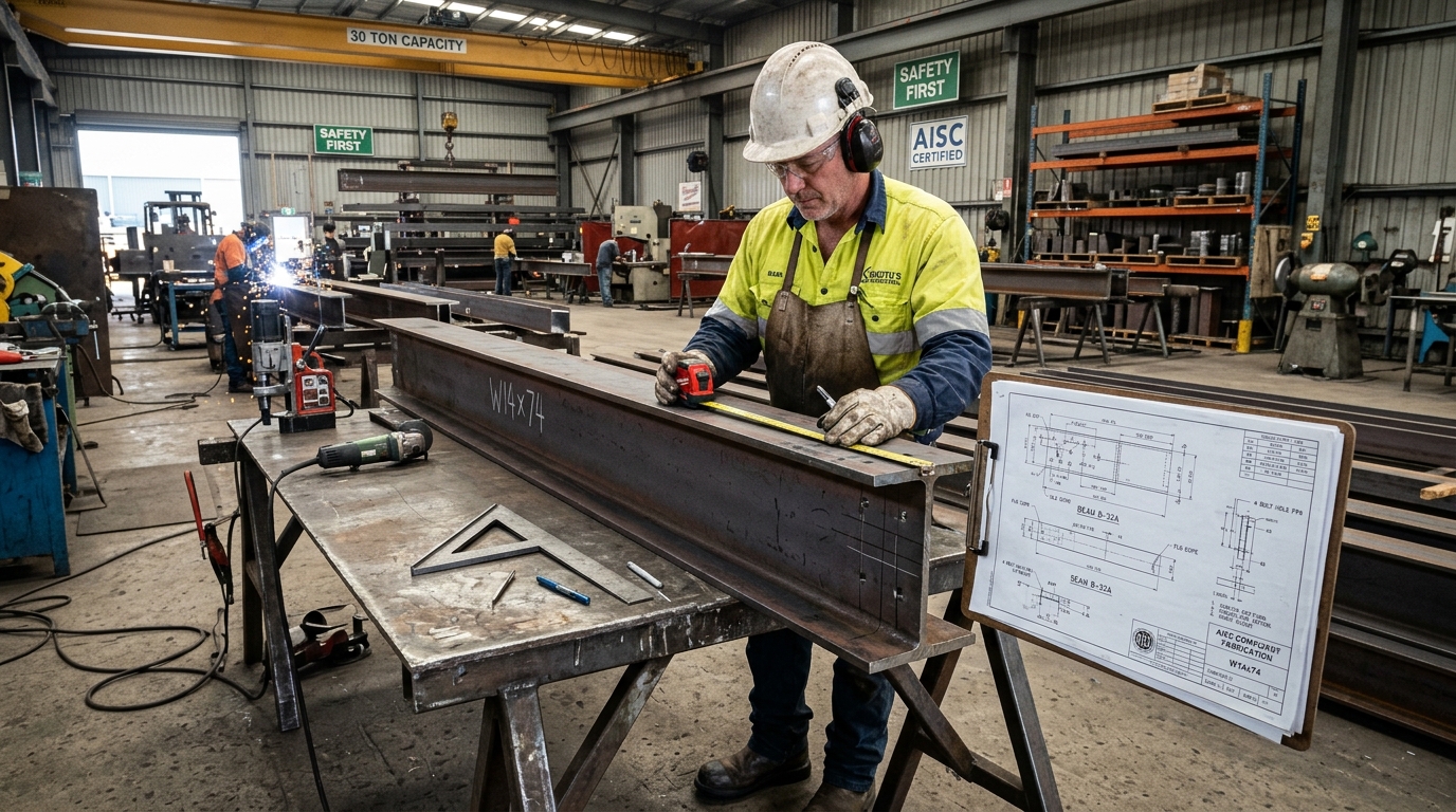
Fabrication drawings are the working instructions for the shop floor. They are produced after approval, from the same model as the shop drawings, but they are organized for production rather than for review. Where a shop drawing groups members for the reviewer's convenience, a fabrication drawing groups them for the cutting line, the drill line, and the welding bay.
A fabrication drawing for a single beam typically shows the exact cut lengths, cope and notch dimensions, hole sizes and locations, weld symbols with sizes and lengths, camber, surface preparation, and paint or galvanizing notes. It also carries the piece mark, the assembly mark, the material grade, and the quantity. On modern jobs, these sheets are paired with CNC data: DSTV files for beam lines, DXF files for plate cutting, and piece tracking in systems such as Tekla PowerFab or FabTrol. The drawing and the CNC file must agree exactly.
Fabrication drawings are rarely submitted to the engineer. That is the most common misunderstanding about them. The engineer approves the shop drawings; the fabricator then produces fabrication drawings as an internal production document. Sending fabrication sheets for approval wastes review cycles, because the reviewer is being asked to approve shop floor instructions that duplicate an already approved design. Keeping the two sets distinct is what lets the approval process stay fast. For a full picture of how detailing feeds production, see our structural steel detailing service, which covers shop, fabrication, and erection deliverables from a single model.
Erection drawings: the field set
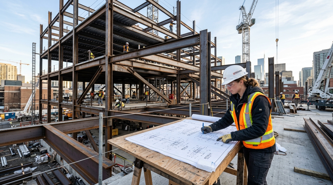
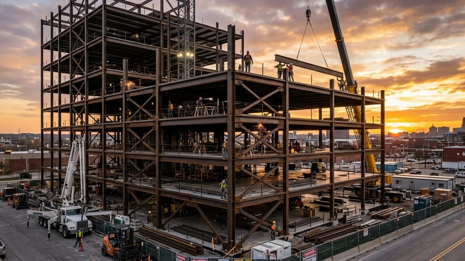
Erection drawings are the field crew's map. They show the structure in plan and elevation, with every member located by gridline, elevation, and piece mark, plus the sequence in which members go up. An erector does not need to know the hole pattern in a beam web. The erector needs to know which piece is which, where it lands, how it connects to its neighbours, what temporary bracing is required, and what field bolts and field welds close the connection.
A good erection set includes framing and erection plans, elevations, field bolt schedules, field weld symbols, anchor bolt setting information, and notes on lifting points, temporary supports, and the shake-out area where delivered steel is staged. Field bolt schedules deserve special attention: they list every bolt the crew must bring up, by size, grade, and quantity, per connection. A missing field bolt schedule is one of the most common reasons a crew loses a day waiting on a delivery that should have arrived with the steel.
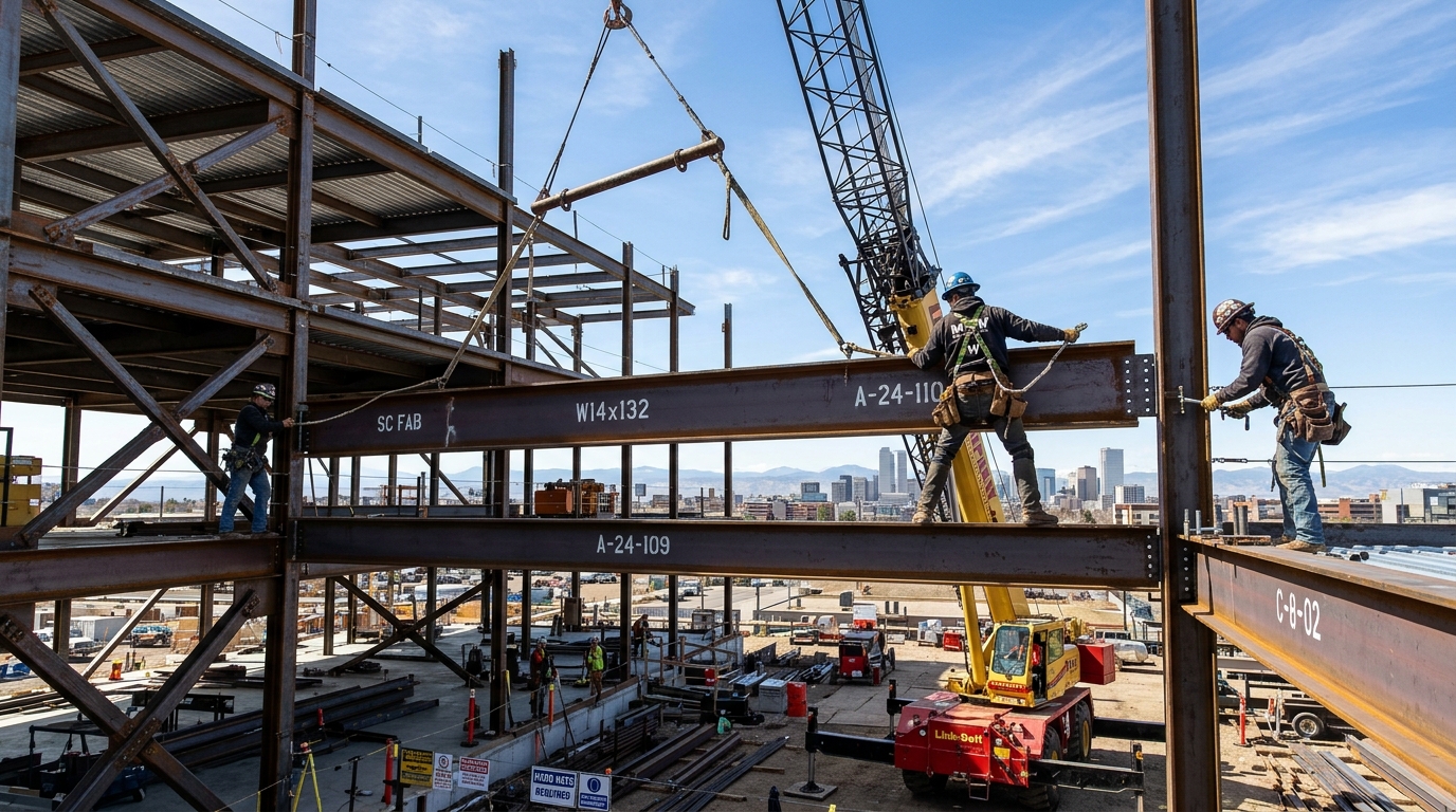
Shop vs fabrication vs erection at a glance
The table below is the quickest way to settle a "which set is this" argument on a job. Pin it to the submittal log, or send it to a new project engineer on their first steel package.
| Question | Shop drawings | Fabrication drawings | Erection drawings |
|---|---|---|---|
| Primary user | Engineer of record, then the fabricator | Shop floor: fitters, welders, CNC operators | Field crew: erectors, foremen, inspectors |
| Main purpose | Prove the design intent is buildable, and get approval | Build every piece exactly right, first time | Place every piece in the right spot, in the right order |
| Level of detail | High: members, connections, dimensions | Highest: cuts, holes, welds, finishes, CNC data | Positional: locations, sequences, field connections |
| Submitted for approval | Yes, to the engineer of record | No, internal production document | Yes, usually with the shop drawing package |
| Piece marks | Assigned and shown | Shown, drives cutting and tracking | Shown, drives field identification |
| Field bolts and welds | Shown as design information | Not the focus | Listed in full: schedules, symbols, quantities |
| Temporary bracing | Noted where design requires it | Not included | Shown, with erection sequence |
| Typical output | PDF submittal set plus model | Shop sheets plus DSTV, DXF, and piece lists | Field set plus field bolt schedules |
Who approves what: the submittal flow
Mix-ups usually start in the submittal log, not on the shop floor. A set labelled "fabrication drawings" gets transmitted for approval, the engineer returns it with comments on shop floor instructions, and three weeks disappear. Or an erection plan is treated as a shop document and never submitted at all, and the field works from an unapproved plan. The flow below keeps the three sets in their lanes.
| Step | Drawing set | Action | Owner |
|---|---|---|---|
| 1 | Shop drawings | Detailer submits the package for review | Detailer to engineer of record |
| 2 | Shop drawings | Engineer reviews and stamps: approved, approved as noted, or revise and resubmit | Engineer of record |
| 3 | Shop drawings | Detailer incorporates review comments and reissues as approved | Detailer |
| 4 | Fabrication drawings | Shop produces fabrication sheets and CNC data from the approved model | Fabricator, no engineer submittal |
| 5 | Erection drawings | Erection set submitted with the shop package, approved, and issued to the field | Detailer to engineer, then to erector |
| 6 | All three sets | Revisions after approval are clouded, logged, and reissued to every holder of that set | Detailer, fabricator, and erector together |
Step 6 is where most jobs quietly fail. A connection changes after approval, the shop gets the revised fabrication sheet, and the field keeps working from the old erection plan. Revision control is not paperwork for its own sake. It is the only thing standing between an approved change and a beam that arrives with the wrong end connection. A shop drawing services provider should be able to show you their revision log format before you award the package.
Five mix-ups that cause rework
These are the five errors we see most often when a new client sends us a package that went wrong on a previous job. Each one traces back to a set reaching the wrong audience.
| Mix-up | What happens | What it costs | How to prevent it |
|---|---|---|---|
| 1. Erection set sent to the shop as the build document | The shop has locations but no cut, hole, or weld detail, so it guesses or stops work to ask | Stalled fabrication, RFIs, rework on guessed details | Release fabrication sheets and CNC data only from the approved model, never from the erection plan |
| 2. Fabrication sheets submitted for approval | The engineer reviews shop floor instructions instead of design intent, and the review drags | Lost review cycles, late steel release | Submit shop drawings for approval. Keep fabrication sheets as an internal production record |
| 3. Field crew working from shop drawings | The crew has member detail but no sequence, bracing, or field bolt schedule | Wrong erection order, missing field bolts, unsafe temporary conditions | Issue the approved erection set as the only controlling field document |
| 4. Piece marks changed between sets | A mark renumbered in fabrication does not match the erection plan or the bill of materials | Wrong pieces shipped, field sorting chaos, crane time wasted | Freeze piece marks at approval. Any renumbering triggers a reissue of all three sets |
| 5. Revisions issued to one set only | The shop builds the revision, the field erects the original, and the connection does not fit | Field modifications, back charges, schedule claims | One revision log, covering all three sets, with a named holder for each |
Piece marks, field bolts, and the handoff between sets
Piece marks are the thread that ties the three sets together. A piece mark is a short code stamped on a member, its fabrication sheet, its line on the bill of materials, and its location on the erection plan. When a truck arrives on site, the erector matches marks on the steel to marks on the erection plan. When a fitter picks up a beam in the shop, the mark on the fabrication sheet matches the mark on the material. One mark, one member, across all three sets, from approval to erection.
Field bolts work the same way, but in reverse: they are specified in the shop drawings, listed in the erection drawings, and almost never appear on fabrication sheets, because the shop does not install them. A field bolt schedule should state the bolt diameter, length, grade, and quantity for every field connection, plus the required pretension method where the design calls for slip-critical joints. If your erection set has no field bolt schedule, ask for one before steel ships.
The handoff that matters most is approval to fabrication. Nothing should be cut before the shop drawings are approved, except long-lead material ordered at the fabricator's risk with the contractor's written agreement. Cutting from unapproved drawings turns every review comment into rework, and the rework lands on finished steel instead of on paper.
What to ask your detailer for before work starts
Use this checklist at the kickoff meeting, before the first submittal is transmitted. It takes ten minutes and prevents most of the mix-ups above.
- Confirm which sets are approval drawings and which are production documents, in writing, in the submittal log.
- Ask for the shop drawing and erection drawing package to be submitted together, so the engineer reviews locations and connections at the same time.
- Confirm fabrication sheets and CNC data will be generated from the approved model, not from an earlier revision.
- Require a piece mark freeze at approval, with a reissue rule for any later renumbering.
- Require a field bolt schedule and an erection sequence with temporary bracing notes in the erection set.
- Agree on one revision log that covers all three sets, with a named holder for each set.
- Agree on the file formats you will receive: PDF sets, plus DSTV, DXF, and piece lists where your shop or field systems need them.
- Confirm the detailer's process for incorporating review comments, and how revised sheets are clouded and transmitted. Our detailing process page describes each stage from model to approved set, so you can compare it with what any provider offers.
Frequently asked questions
Are shop drawings and fabrication drawings the same thing?
No, although the terms are often used interchangeably, and that loose usage causes real problems. Shop drawings are approval drawings submitted to the engineer. Fabrication drawings are the shop floor production set, made after approval. On small jobs, one provider may produce both from the same model, which is fine, but the sets should still be labelled and transmitted separately, so the approval process and the production process stay distinct.
Does the engineer approve erection drawings?
Yes, in most US practice erection drawings are submitted as part of the shop drawing package and reviewed by the engineer of record, who checks member locations, field connection types, and bracing assumptions. Confirm this on your specific project, because contract requirements vary, but never assume the erection set can go to the field unreviewed.
Can the field crew work from shop drawings if the erection set is late?
Only as a stopgap, and only with the engineer's written agreement. Shop drawings do not show erection sequence, temporary bracing, or field bolt schedules, so working from them alone risks out-of-sequence erection and missing field hardware. The correct fix is to expedite the erection set, not to normalize working without it.
Who owns piece marks: the detailer or the fabricator?
The detailer assigns piece marks in the model, and the fabricator and erector use them unchanged. If a fabricator's internal system needs different numbering, it should be mapped to the detailer's marks, not substituted for them, so the erection plan, the bill of materials, and the steel on the truck all agree.
Final check before you release a package
Three sets, three audiences, one model. If you remember nothing else from this article, remember the transmission test: before any set leaves your office, ask who will use it and what decision they will make from it. If the answer is the engineer approving design intent, it is a shop drawing. If the answer is the shop building a piece, it is a fabrication drawing. If the answer is the crew placing steel in the field, it is an erection drawing.
If you are planning a steel package and want the three sets produced from a single coordinated model, with a revision log that keeps them in step, request a fixed proposal and send your design drawings for review. We will confirm scope, deliverables, and turnaround before any work starts.