
Miscellaneous Metals Detailing Services
From fabricated steel stairs and architectural railings to access ladders, platforms, catwalks, and custom metal components, our miscellaneous metals detailing services help US contractors and fabrication shops organize the drawings needed for production, review, and installation. Share your contract documents and fabrication requirements for a scope-specific drawing proposal.
Core Detailing Capabilities:

Fabrication & Erection Documentation
Custom stair stringers, landing supports, guardrail post mountings, and wall returns detailed to contract specifications.
Assembly Layout & Interface Coordination
Clear callouts for dimensions, member marks, and mounting substrates.
Scope & Purpose
Detailed Shop Drawings for Custom and Standard Metal Elements
Miscellaneous metals detailing is the preparation of project-specific drawings for metal assemblies and components outside the main structural framing package or assigned to a separate specialty-metal scope. Common examples include steel stairs, handrails, guardrails, ladders, grating platforms, canopies, bollards, embeds, and architectural metal features.
These components often connect to structural steel, concrete, masonry, or finished architectural surfaces. A drawing package must therefore communicate more than the shape of an individual part. It should identify relevant dimensions, member and material information, attachment locations, assembly references, and the interfaces between the fabricated item and the surrounding building.
For contractors and fabricators, well-organized miscellaneous metal drawings provide a common reference during submittal review, material preparation, shop production, and field installation. Where contract information is incomplete or inconsistent, unresolved dimensions and connection requirements should be identified for clarification before fabrication.
The exact scope depends on the contract documents and approved project requirements.
Common Scopes
Miscellaneous Metal Shop Drawings Across Common Construction Applications
Miscellaneous metals packages vary widely between commercial, industrial, institutional, and architectural projects. The categories below represent common drawing scopes. Individual deliverables depend on the assigned trade package and project specifications.
Steel Stairs
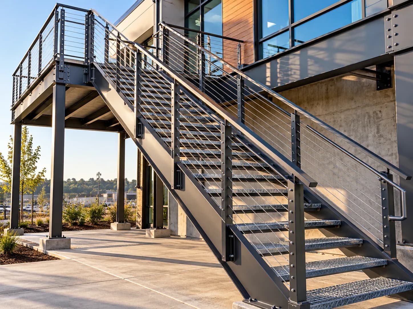
Stair arrangement drawings, landing interfaces, stringers, treads, risers, support brackets, and related fabrication details.
Railings and Guards
Guardrail elevations, post spacing, infill arrangements, transitions, attachment details, and material references.
Fixed Ladders
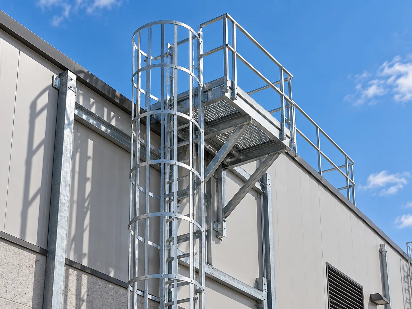
Ladder layouts, rung and rail details, mounting brackets, access clearances, and project-specific safety system interfaces.
Handrails
Wall-mounted and stair-mounted handrail layouts, returns, bracket locations, and attachment information.

Canopies
Metal canopy framing, member layouts, support brackets, connection locations, and coordination with building finishes.
Platforms and Mezzanine Components
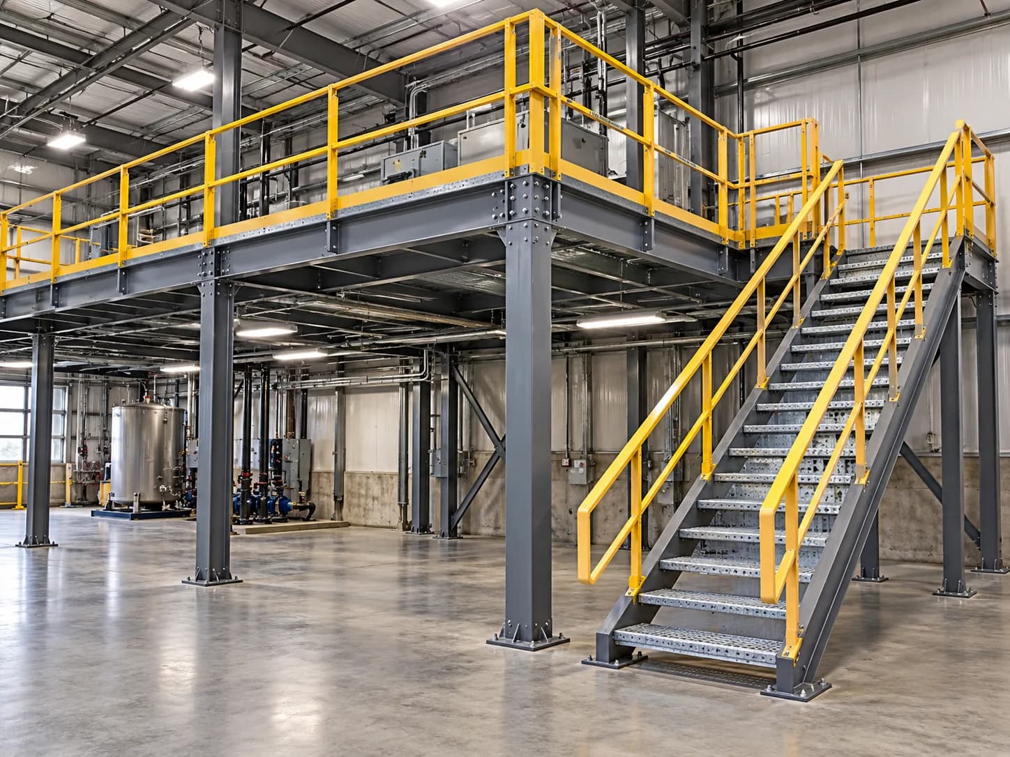
Access platforms, deck framing, support members, grating, guardrails, and equipment-interface details. Structural engineering and load design remain outside standard drafting scope unless separately authorized.

Catwalks and Grating
Walkway arrangement drawings, grating panels, bearing supports, openings, edge trims, and handrail coordination.
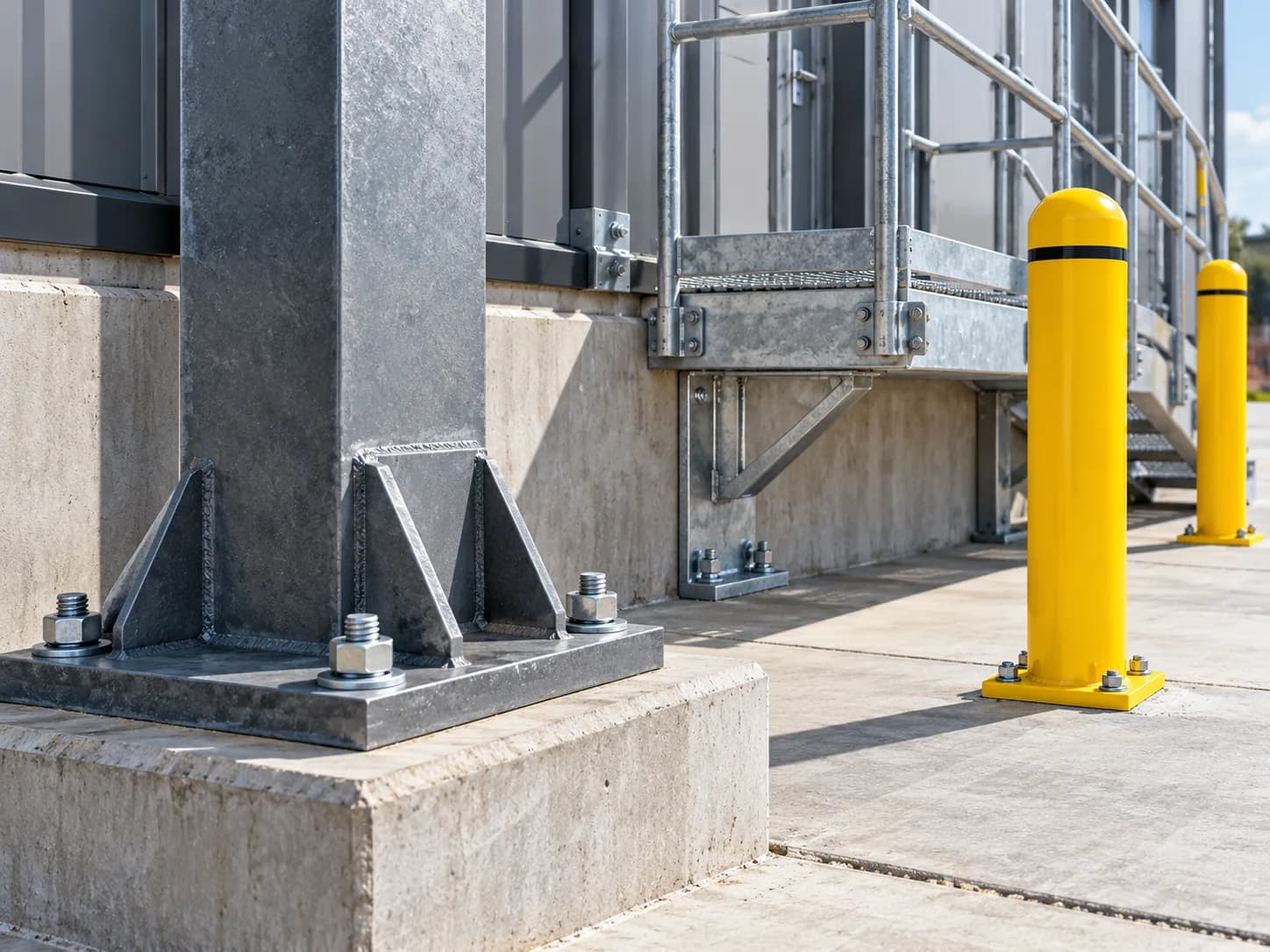
Bollards, Embeds and Plates
Bollard arrangements, base plates, embedded plates, anchor references, and interfaces with concrete or finished surfaces.
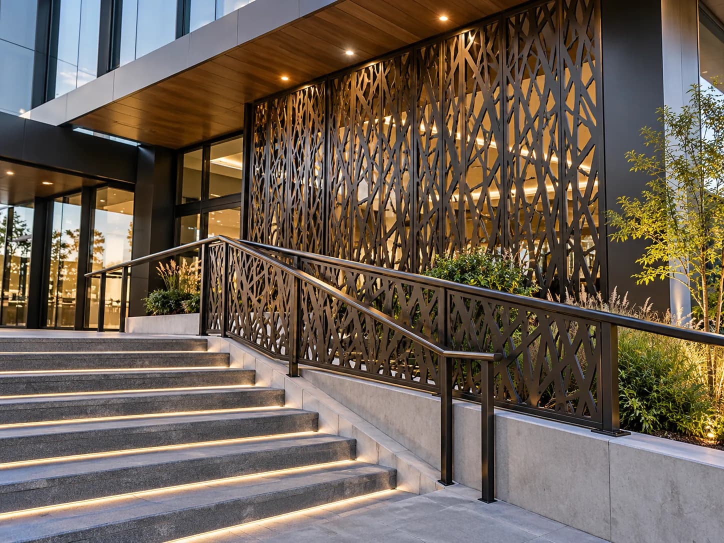
Ornamental Metalwork
Decorative metal screens, architectural panels, custom railing patterns, and fabrication details based on approved design information.
Custom Fabricated Metal Items
Specialty brackets, frames, supports, metal assemblies, and other project-specific items defined in the contract scope.
Looking for primary structural framing packages? View our Structural Steel Detailing Services or explore our comprehensive Trade Services Directory.
Technical Documentation
What Goes Into a Useful Miscellaneous Metal Drawing?
The information required on a drawing depends on the item being fabricated. A stair flight needs different views and coordination information than a bollard, an architectural screen, or a fixed ladder. The goal is to document the approved geometry and the details necessary for the assigned fabrication scope.
Arrangement and Setting-Out Information
Arrangement drawings identify the component's intended location, overall configuration, reference grids or levels, major dimensions, and relationship to nearby structural and architectural elements. Stair and platform layouts should coordinate with floor levels, openings, landings, and supporting surfaces shown in the contract documents.
Component and Assembly Drawings
Fabrication views organize individual parts into assemblies. Depending on the component, these sheets may show stringers, brackets, posts, plates, rails, supports, grating edges, part marks, material sections, and assembly references. The required fabrication dimensions must follow the approved scope and source information.
Connections and Attachment Details
Connections are a frequent coordination point in miscellaneous metal packages. Drawings should identify approved plate arrangements, bolt or weld references, mounting locations, and interfaces with concrete, masonry, structural steel, or other construction. Any connection design requiring engineering must come from the responsible design professional or approved delegated designer.
Finishes and Material References
Shop documentation should reflect the project-specified material and finish requirements. Relevant items may include steel grades, stainless steel or aluminum specifications, protective coatings, galvanizing, finish transitions, and areas requiring special fabrication or installation coordination.
Deliverable Scope
What a Miscellaneous Metal Shop Drawing Package May Include
The final drawing package is established during scope review. Depending on the item and fabrication method, a typical deliverable set may contain the following documents.
1. General Arrangement Drawings
Plans, elevations, sections, reference levels, overall dimensions, and component placement across building interfaces.
2. Fabrication and Assembly Drawings
Member and part marks, individual part references, assembly geometry, and shop fabrication notes.
3. Connections and Anchor Details
Approved mounting arrangements, plates, holes, bolts, weld references, and substrate interfaces.
4. Material and Component Schedules
Item descriptions, part quantities, material references, and organized lists where included in scope.
5. Installation Reference Drawings
Placement references, assembly locations, and field coordination information relevant to the supplied package.
6. Model and Digital Outputs
3D views, CAD files, or machine-data exports where requested, supported, and included in the agreement.
Note: Deliverables are project-specific. CNC output, calculations, engineered connections, or 3D models are confirmed during contract agreement.
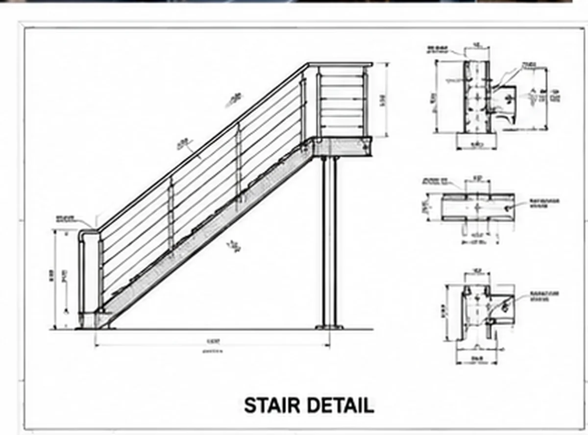
Coordinated Stair & Railing Shop Sheet
Stringers, treads, and railing mounts detailed for field fit.
Egress & Architectural Clearances
Coordinating Stair, Railing and Handrail Details
Stair and railing assemblies frequently cross several construction interfaces. Finished floor elevations, supporting steel, slab edges, wall finishes, and required clearances all influence the final geometry.
For stair packages, relevant drawings often address total rise, flight arrangement, landing dimensions, stringer positions, tread construction, support locations, and connections to adjacent structural elements.
Railing and handrail drawings may require post layout, mounting type, infill arrangement, profile dimensions, transitions, returns, and finish requirements.
Building-code and accessibility requirements depend on the building's use, jurisdiction, adopted codes, and applicable project standards. A handrail requirement for an accessible public stair must not be assumed identical to an industrial guardrail requirement.
Any discrepancy between contract drawings, site dimensions, and specified code criteria must be referred to the responsible project parties for resolution.
| Drawing topic | Information to coordinate |
|---|---|
| Stair geometry | Rises, runs, landings, levels and support points |
| Guardrail layout | Post positions, infill, openings and connections |
| Handrail layout | Mounting locations, returns and clearances |
| Substrate interface | Steel, concrete, masonry and wall finish conditions |
| Material and finish | Profiles, grades, coating and fabrication requirements |
Industrial Access
Detailing Industrial Access and Maintenance Metalwork
Industrial and maintenance-access components often require additional coordination around equipment, access routes, platforms, service clearances, and supporting structures.
A fixed ladder package may include rung and side-rail geometry, wall brackets, platform transitions, mounting locations, and interfaces with the specified fall-protection system.
For platforms and catwalks, detailing may address framing layouts, grating panels, support connections, access openings, guards, toe boards, and coordination with adjacent machinery or pipework.
The responsible design professional and project specifications determine structural loading criteria and engineered requirements. Safety provisions depend on the intended use and applicable regulations.
A ladder cage is not a universal substitute for a required ladder safety or personal fall-arrest system. Specific OSHA and site fall-protection requirements must be confirmed by the project safety authority.
Fixed LaddersCatwalks & GratingQuotation Preparation
What We Need to Prepare Your Miscellaneous Metals Drawing Quote
A clear document package helps define the work before detailing starts. For projects with several metal assemblies, a marked scope schedule is especially useful.
If some details are missing, identify them when sending your request. Unresolved scope or design information may need clarification before a reliable detailing schedule is confirmed.
Submittal Verification
Comprehensive cross-checking between architectural plans and structural details.
Workflow & Coordination
From Project Documents to a Coordinated Drawing Package
Our systematic drafting process coordinates your miscellaneous metal drawings from initial submittal review to shop-ready production packages.
Review the Scope
Review contract drawings, specifications, fabrication requirements, relevant revisions, and assigned miscellaneous-metal items.
Resolve Document Questions
Identify missing dimensions, conflicting details, unclear attachment conditions, and other information requiring an RFI or project-team clarification.
Prepare Drawings
Organize arrangement views, fabrication sheets, assembly details, and required schedules based on the confirmed scope.
Check and Revise
Review drawing references and consistency, then incorporate authorized submittal comments or design revisions according to the agreed revision process.
Issue Deliverables
Provide the agreed drawing set and related files in the specified format for the next contractual review, fabrication, or coordination stage.
Interested in our wider construction coordination process? Read more on our Five-Stage Detailing Methodology.
Sample Drawings
Miscellaneous Metals Shop Drawing Examples
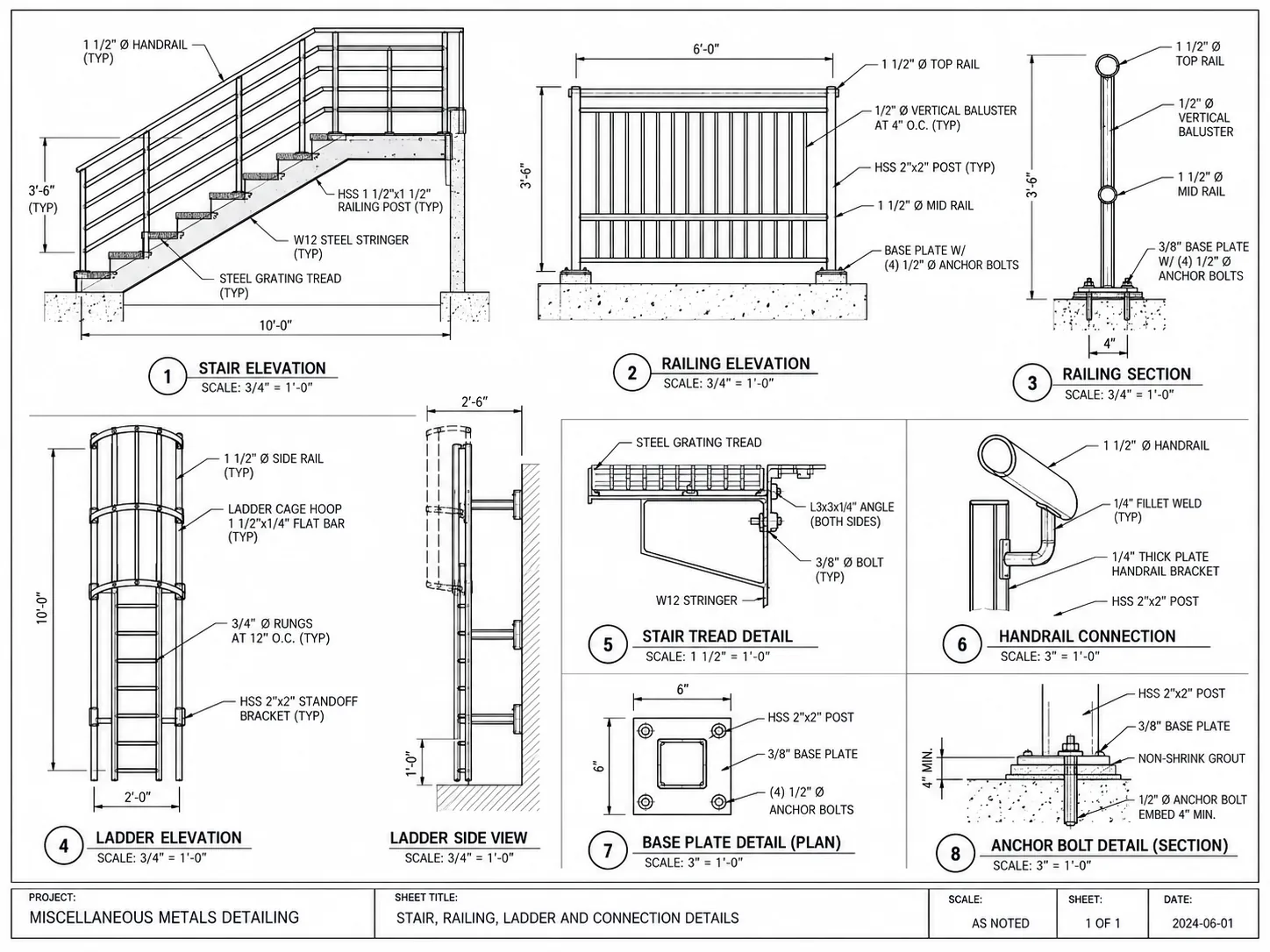
Review illustrative examples of common miscellaneous metal drawing packages. These samples demonstrate the types of plans, elevations, sections, and component details that may appear in a project-specific deliverable set.
STAIR & HANDRAIL ASSEMBLY SHEET
Scale: 1/2" = 1'-0"Stair and Handrail Shop Drawing
Conceptual stair and handrail documentation showing the overall stair configuration, guard details, connection references, and component views.
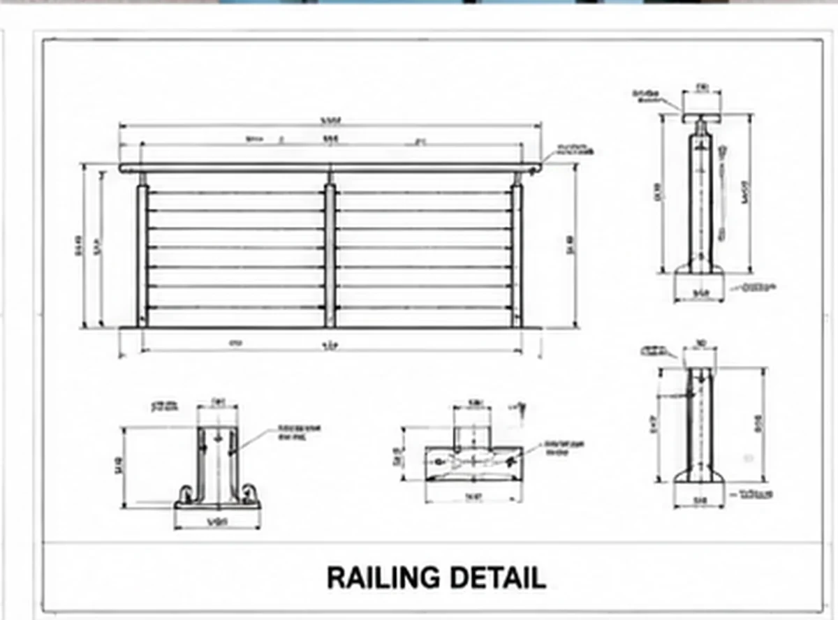
GUARDRAIL ELEVATION & MOUNTING DETAIL
Scale: 3/4" = 1'-0"Guardrail Shop Drawing
Illustrative railing elevations and post connection details, including mounting arrangements and component references.
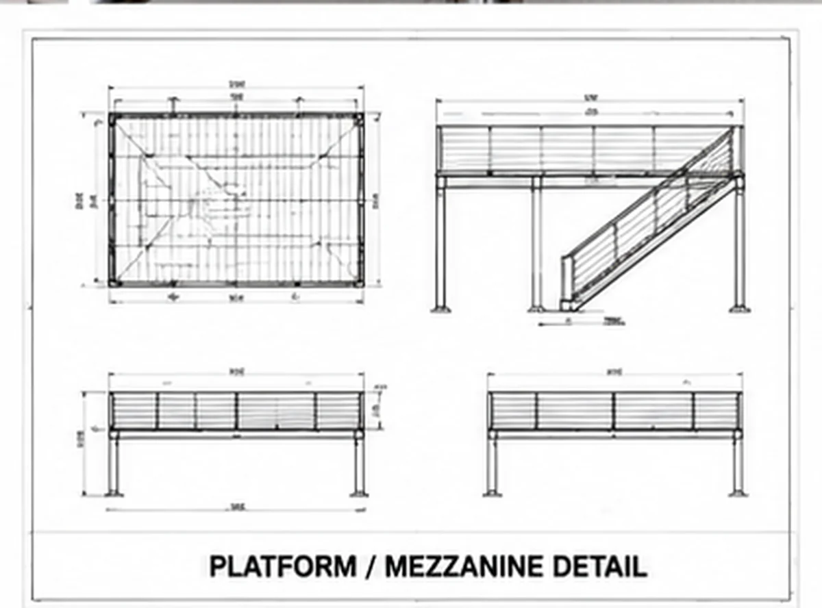
ACCESS PLATFORM & DECK FRAMING SHEET
Scale: 1/4" = 1'-0"Platform and Mezzanine Detail
Conceptual industrial platform documentation showing support framing, access arrangements, grating and guardrail interfaces.
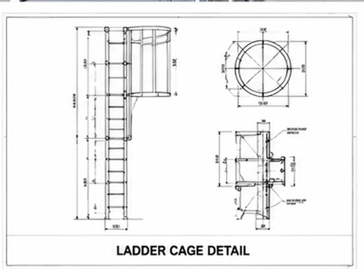
FIXED LADDER & ACCESS GEOMETRY
Scale: 1/2" = 1'-0"Ladder Cage and Access Detail
Illustrative fixed-ladder and access-platform views demonstrating geometric and mounting details. Applicable fall-protection requirements must be established separately.

Quality Assurance Protocol
Member marks, connection clearances, and elevation verification before issue.
Quality Assurance
Drawing Checks Focused on Fabrication and Installation Coordination
Miscellaneous metal assemblies require particular attention to fit and interface conditions. A drawing review should compare the proposed fabrication information with relevant architectural and structural documents, approved design details, and the most current project revisions.
Potential coordination issues include inconsistent finished-floor elevations, railing posts conflicting with slab edges, missing anchor information, interference with finishes, and differences between drawing dimensions and verified field conditions.
Before drawings are issued, the package should be checked for completeness, consistent part references, relevant material descriptions, and clearly identified outstanding questions.
These documentation checks support the submittal and fabrication process. They do not replace licensed engineering, construction inspections, or mandatory project approvals.
Scope Check Focus Areas:
Learn more about our comprehensive checking protocols on our dedicated Quality Assurance Overview.
Industry Standards
Applicable Standards and Responsibility Boundaries
Miscellaneous metal assemblies may fall under different codes and specifications according to their location and intended use.
Commercial stairs, guards, and handrails are governed by applicable adopted building codes and accessibility provisions. Industrial walking-working surfaces, fixed ladders, and workplace guardrails may have additional OSHA requirements.
Relevant welding, materials, fabrication, or structural steel standards depend on the component and contract scope.
The AISC Code of Standard Practice distinguishes several miscellaneous-metal items from ordinary structural steel scope. The assigned responsibilities should therefore be confirmed from the actual contract documents rather than assumed from a general service description.
Our detailing scope is the preparation and coordination of assigned drawing information. Structural design, delegated connection engineering, professional stamping, and final code approval are outside standard detailing services unless separately agreed with appropriately qualified professionals.
Applicable Reference Sources & Industry Standards:
Governing definitions for structural steel vs. miscellaneous steel scope demarcation and approval submittal procedures.
Federal safety criteria for industrial stair tread depths, uniform rise heights, railing heights, and clearance dimensions.
Standard criteria for guardrails, handrails, toeboards, and walking-working surface safety barriers.
Standards are referenced for coordination guidance. ShopDrawingServices.us prepares drawing documentation and does not provide certified professional engineering unless contracted through authorized licensed partners.
Deliverables & Compatibility
Drawing and Model Deliverables
Deliverables are confirmed during scope review. Typical drawing packages are issued as PDF files for review and distribution, with editable CAD or model-based outputs where required by the project and supported by the agreed workflow.
Possible formats include PDF, DWG, DXF, IFC, and appropriate model or schedule exports. File availability depends on the specific component, software workflow, and contractual deliverables.

Vector PDF
Submittal Booklets & Shop Prints

AutoCAD .DWG
Editable 2D CAD Layouts

DXF Profiles
Plate & Component Profiles

IFC 3D BIM
Open BIM Model Coordination

3D Isometric Views
3D Perspectives & Visuals

CSV / Excel Schedules
Material & Cut Lists
Review the complete software platforms we support on our Supported Detailing Software Page.
Sectors Served
Miscellaneous Metals Detailing for Commercial and Industrial Construction
Miscellaneous metal assemblies are used throughout the built environment, from architectural stairs and decorative screens to access platforms and industrial maintenance systems.
Commercial Buildings
Stairs, guards, canopies, architectural metalwork, and equipment access.
Industrial Facilities
Platforms, catwalks, fixed ladders, grating, and maintenance access.
Institutional Buildings
Stairs, handrails, accessible circulation interfaces, and specialty metalwork.
Healthcare Buildings
Architectural guardrails, support assemblies, access components, and finish-sensitive details.
Hospitality and Retail
Decorative screens, feature railings, canopies, and custom architectural metals.
Infrastructure and Utility Projects
Industrial access platforms, support steel, ladders, guards, and maintenance assemblies.
Working as a prime contractor? Visit our dedicated General Contractors Detailing Hub or browse all Construction Industries We Support.
Estimating & Turnaround
What Affects Miscellaneous Metals Detailing Cost?
Miscellaneous metals detailing is generally quoted according to the actual drawing scope, not a universal price per sheet.
A project with a small number of repetitive railing panels differs substantially from one containing custom stair assemblies, decorative screens, complex attachment conditions, and several design-review cycles.
Key estimating factors include the number of unique components, geometry, connection complexity, available project information, required modeling, fabrication preferences, and revision scope.
During preconstruction planning, general contractors and fabricators often coordinate material takeoffs alongside detailing packages. For broader project budgeting, teams frequently utilize construction cost estimating and quantity takeoff services to forecast division 05 metalwork expenses accurately before drawing production starts.
Provide the drawings, specifications, and requested submittal dates so the work can be reviewed and priced against the correct deliverables.
Key Scope & Pricing Factors:
Ready for a Scope Review?
Send your drawing sheets and specs for a scope-tailored quotation with itemized deliverable commitments.
Request a QuotationCommon Questions
Miscellaneous Metals Detailing FAQs
Clear answers regarding drawing scopes, deliverables, source documents, and project coordination.
The scope may include arrangement drawings, fabrication and assembly details, connection references, material information, and installation-related views for the metal components listed in the contract. Deliverables are confirmed before work begins.
Have a question not addressed here? Check our comprehensive Sitewide Detailing FAQ Center or contact our team directly.
Start Your Drawing Submittal
Let's Discuss Your Miscellaneous Metals Detailing Project
Send your drawings, specifications, and metalwork scope for review. Receive a project-specific quotation based on the required assemblies and drawing deliverables.