
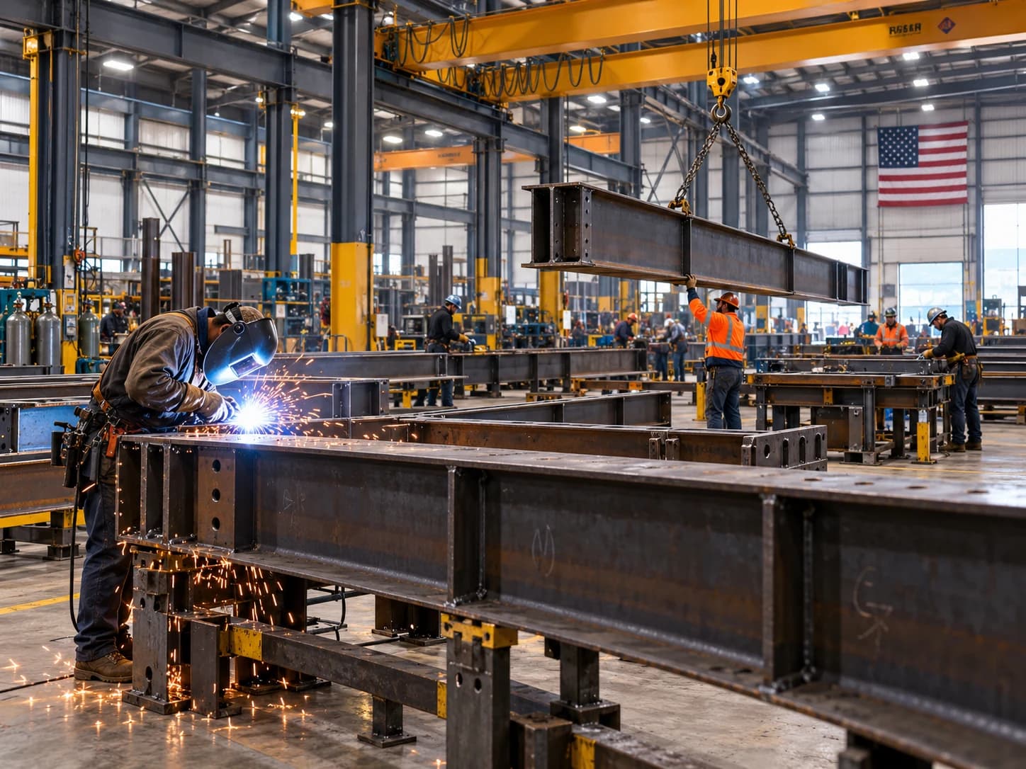
Steel Fabrication Drawings for Structural Steel Fabricators
Precision shop-ready fabrication drawings, beam and column assembly sheets, single-part cut profiles, and CNC DSTV files engineered for US steel fabricators and manufacturing shops. Every drawing details exact piece marks, hole gauges, bevel cuts, and AWS weld symbols to eliminate shop floor fitting errors and costly rework.
AISC 303 Section 6
Strict adherence to US shop fabrication, camber, sweep, and mill bearing tolerances.
CNC DSTV & DXF
Automated drill, saw, and plasma machine files exported directly from 3D models.
Single-Part Cut Sheets
Unique piece marks, plate nesting profiles, and advance cut lists for efficient stock usage.
AWS D1.1 Welding
Clear welding callouts, backing bar notes, and explicit shop vs field weld delineation.

3D Fabrication Modeling: Member geometry, bolt hole layout & cope checking
What Steel Fabrication Drawings Include and How They Guide the Shop Floor
While structural design drawings define member sizes and structural loads for the Engineer of Record (EOR), steel fabrication drawings translate that design intent into direct manufacturing instructions for shop fitters, saw operators, and certified welders.
A steel fabrication package breaks down every wide-flange beam, tube column, diagonal brace, and miscellaneous clip into granular, cut-and-weld instructions. Each sheet contains exact dimensions, hole gauges, flange copes, edge bevels, piece marks, and bill of materials (BOM) needed to fabricate structural steel with zero ambiguity.
Clear Separation of Shop vs. Field Scope
Every hole and weld is explicitly identified as either shop-completed or field-installed, preventing dangerous omissions and avoiding redundant shop labor.
Alphanumeric Piece Marking System
Major assemblies receive main piece marks (e.g., B101, C204), while constituent single parts receive distinct sub-marks (e.g., p10, a12) corresponding to cut lists and nesting profiles.
Standardized Material Grade Callouts
Specifications mandate ASTM A992 for wide-flange shapes, ASTM A500 Grade B/C for HSS tubes, ASTM A36 / A572 Gr. 50 for plates, and ASTM F3125 Grade A325/A490 for bolts.
The Complete Steel Fabrication Drawing Package
Our steel fabrication packages provide every drawing and data format necessary to move steel from raw mill shapes to fully inspected, painted, and sequence-shipped assemblies.
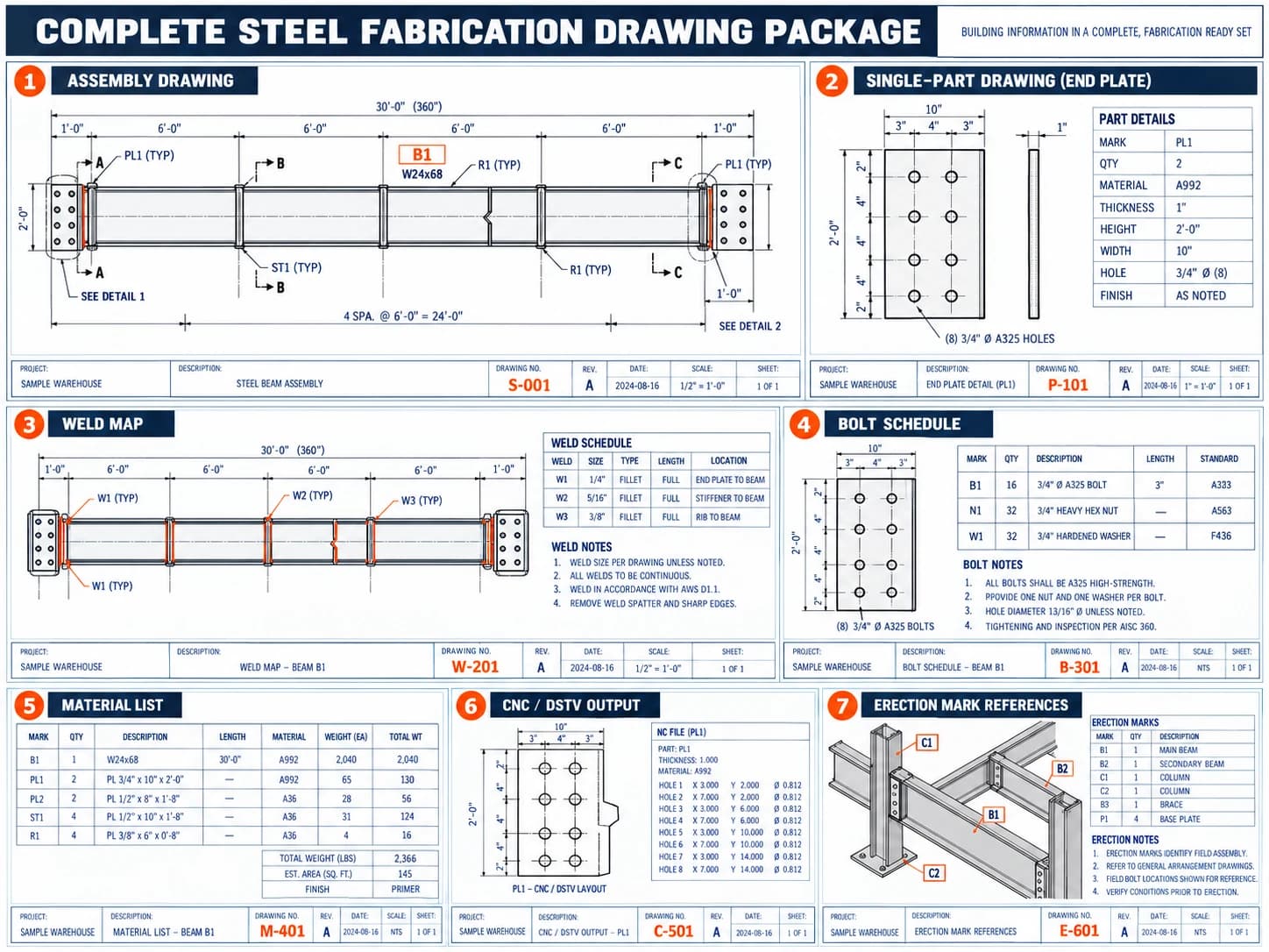
Typical Shop Drawing Package Layout
Integrated assembly elevation, 3D isometric view, single-part details, and advance bill of materials.
| Package Component | Shop Floor Function | Primary Audience |
|---|---|---|
| Beam Assembly Sheets | Wide-flange member cut lengths, flange copes, shear tabs, camber requirements, and piece marks. | Saw operators & fitters |
| Column & Base Plate Sheets | Multi-story column shaft lengths, milled end bearing notes, splice plates, and anchor rod patterns. | Layout fitters & welders |
| Single-Part Cut Sheets | Granular dimensioning for clip angles, stiffeners, gusset plates, and shear tabs with piece tags. | Plate burning & shear crews |
| Advance Bill of Materials (ABM) | Tonnage summaries, cut lists, section weights, and ASTM material specifications for purchasing. | Purchasing & inventory |
| CNC DSTV & DXF Files | Machine-ready NC code for automated drill lines, coping machines, and CNC plate cutting tables. | CNC machine programmers |
Beam Fabrication and Assembly Detailing
Wide-flange beams (ASTM A992) represent the bulk of tonnage in commercial framing. Our beam fabrication sheets provide exact geometric dimensioning to prevent interference with columns, adjoining girders, and architectural finishes.
Top-of-Steel (TOS) & Camber Ordinates
Clear callouts for specified mill camber (e.g., 1-1/2" camber at midspan) and running dimensional strings referenced from the left end of the member to verify overall length tolerances.
Cope Geometry & Re-Entrant Radii
Flange copes detailed with strict compliance to AISC 303 Section 6.5, specifying smooth transition curves with a minimum 1/2-inch radius to eliminate stress risers that cause brittle cracking.
Standardized Hole Clusters & Stiffeners
Web hole spacing verified against AISC Table 10-1 standard gauges, with web stiffeners and doubler plates detailed with weld preps and corner clips for weld clearance.
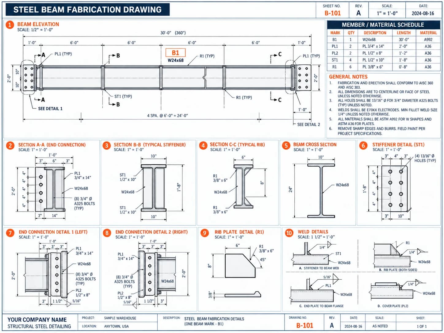
W-Shape Beam Assembly Sheet
Flange copes, shear tab welding & bolt hole patterns
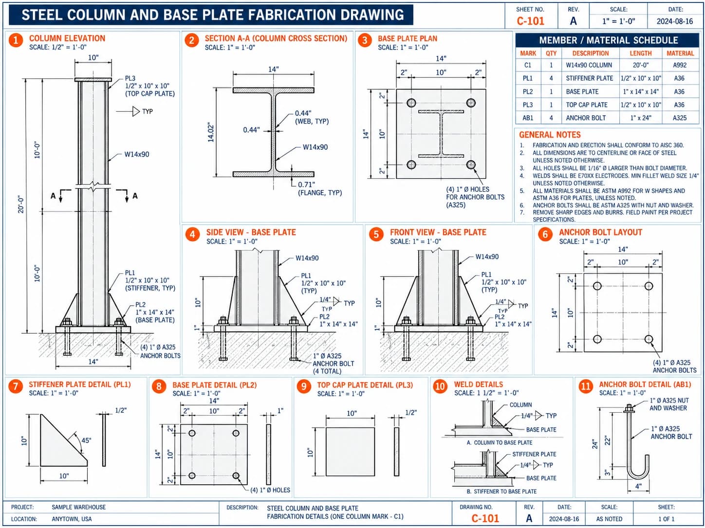
Column Assembly & Base Plate Detail
Anchor bolt pattern, milled end bearing & splices
Column Assembly, Splices & Base Plate Detailing
Structural columns bear the full vertical gravity and lateral overturning loads of a building. Detail errors on columns stop multi-tier erection in its tracks. Our column sheets coordinate foundation anchor rods, milled end bearings, beam connection seats, and multi-tier field splices.
Milled End Bearing & AISC 303 Section 6.2
Compression columns finished to bear require saw cut or milled end tolerances conforming to AISC 303 Section 6.2, maintaining true 90-degree squareness and contact bearing.
Heavy Base Plates & Anchor Rod Templates
Base plates detailed per AISC Design Guide 1 with oversized anchor rod holes (e.g., 1-5/16" holes for 1" anchor rods) to absorb foundation setting variations, complemented by heavy washer plates.
Multi-Tier Field Splices & Erection Lift Lugs
Bolted and welded column splices positioned typically 3 to 4 feet above finished floor levels for ironworker accessibility, complete with lift holes and crane rigging clearances.
Connection, Gusset, Weld & Bolting Details
Connections represent up to 60% of shop fabrication labor. Clean, standardized connection details prevent fit-up failures and ensure rapid erection. Our drawings detail every single-plate shear tab, moment connection, seated angle, and heavy brace gusset.
Important Engineering Scope Clarification: Steel fabrication detailers develop connection geometries based on contract documents and standard AISC reaction tables. Detailers do not perform licensed structural design. Where delegated connection design is required by the project specifications, calculations must be sealed by a registered Professional Engineer (PE/SE).
AWS D1.1 Standard Welding Callouts
Fillet welds, complete-joint-penetration (CJP) groove welds with backing bars, and partial-joint-penetration (PJP) welds clearly distinguished with proper AWS A2.4 symbols.
RCSC Bolt Spacing & Edge Distance Verification
All bolted connections verified against AISC 360 Table J3.4 minimum edge distances (e.g., 1-1/4" sheared edge distance for 3/4" bolts) and verified for pneumatic torque wrench clearances.
Uniform Force Method (UFM) for Bracing Gussets
Heavy vertical and horizontal bracing gusset plates detailed per the AISC Uniform Force Method to eliminate eccentric moments at beam-to-column intersections.
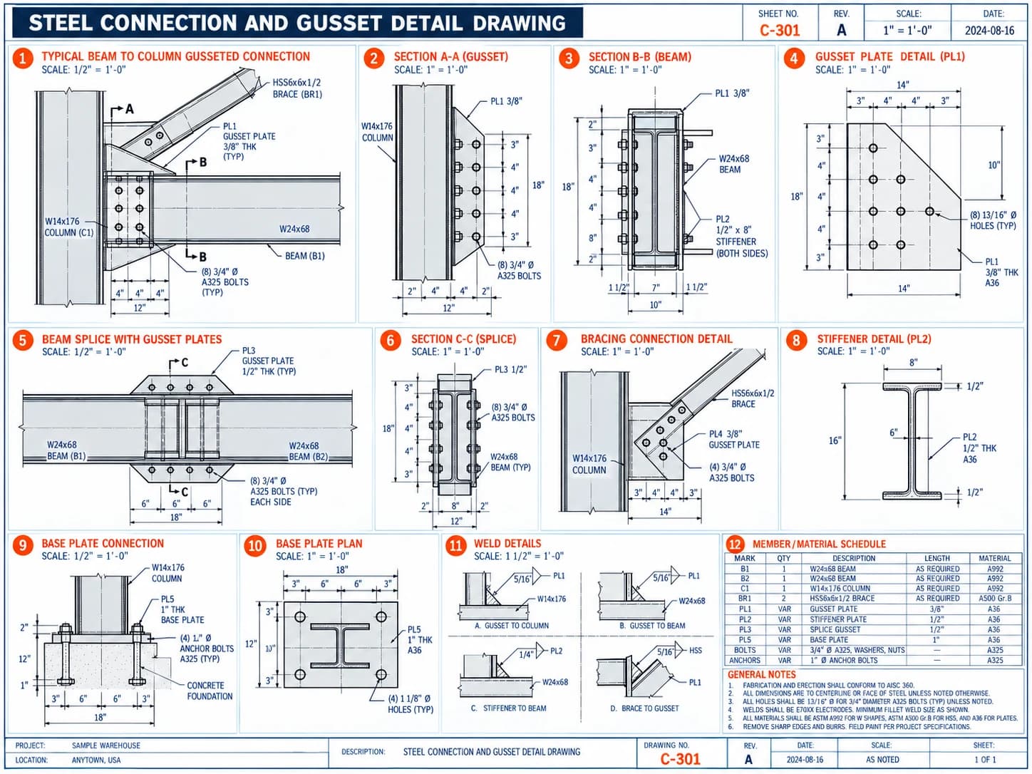
Gusset & Bracing Detail Sheet
Whitmore section analysis, bolt pitch & weld symbols
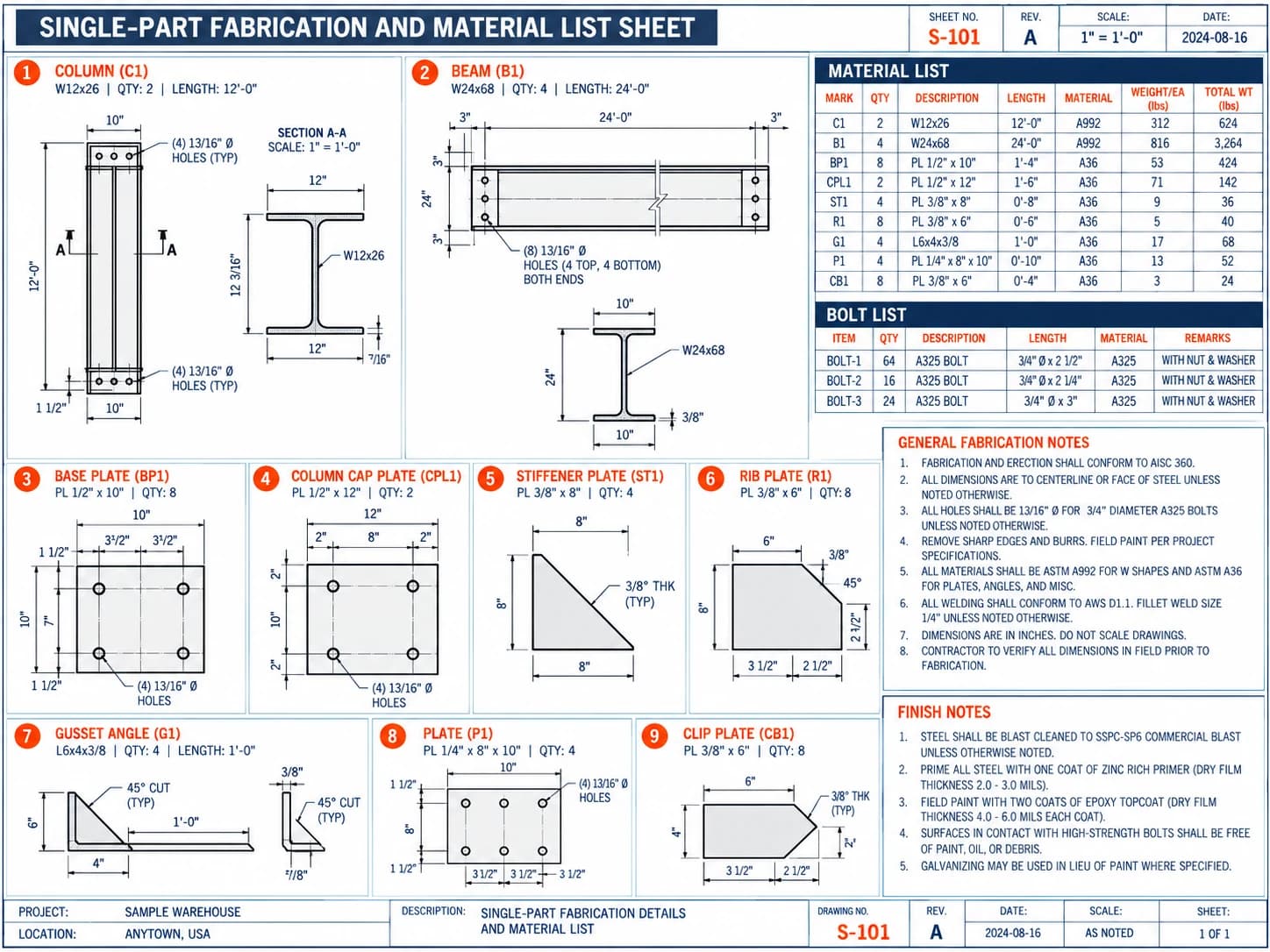
Single-Part Cutting Schedule
Part marks, hole drill coordinates & plate nesting
Single-Part Cutting Schedules & Advance Material Lists
Before fitters can assemble a beam or column, individual plates, clip angles, stiffeners, and base plates must be sheared, sawed, punched, or burned. Our single-part detail sheets provide dedicated shop drawings for every loose piece.
Unique Part Mark Indexing
Parts receive unique alphanumeric tags (e.g., `p1`, `a12`, `cp5`) stamped on steel to streamline sorting from burning table to fit-up jigs.
Plate Nesting Optimization
Cut dimensions formatted for standard plate nesting software, reducing drop waste and maximizing stock sheet yield.
Center-to-Edge Coordinates
Hole layouts dimensioned from true reference edges, allowing punch operators to set back-gauges rapidly with zero manual math.
Advance Mill Ordering (ABM)
Linear cut lists and exact tonnage tallies delivered early so purchasing teams can secure mill steel without delays.
Our 5-Stage Steel Fabrication Workflow
From contract drawings to released CNC files, every project moves through a strict 5-stage detailing and QA protocol to ensure 100% fit-up accuracy on the shop floor.
Contract Review & RFI Resolution
Inspection of architectural and structural sheets, specification section 05 12 00, and addenda. We identify discrepancies early and submit formal Requests for Information (RFIs) to the structural engineer.
3D BIM Model & Shop Drawing Generation
Structural geometry, member profiles, connections, and hardware are fully modeled in 3D. 2D assembly sheets, single-part details, and bills of material are automatically extracted from the synchronized model.
Shop Verification & EOR Submittal Review
Drawings are reviewed internally by senior checkers and submitted to the GC and Engineer of Record. Review stamps (Approved / Approved as Noted) are cataloged before steel is released.
Delta Revision Tracking & Clouding
Any design change or field revision is marked with formal delta revision clouds (▲1, ▲2) and documented in the title block. Fabricators can immediately identify modified members versus unchanged steel.
Release for Fabrication & CNC Delivery
Final approved drawing packages (PDF/DWG), DSTV (.NC1) machine files, DXF plate burn files, and cut lists are delivered directly to the fabricator for immediate shop floor execution.

Rigid Quality Verification Gate
Every drawing verified by senior structural detailing checkers prior to release

Automated CNC Production Integration
DSTV (.NC1) drill line programming & DXF plate cutting files
From 3D CAD Model to CNC & DSTV Automated Fabrication
Modern US fabrication shops rely heavily on automated beam drill lines, robotic plasma copers, and CNC plate burning tables. Manual layout with a tape measure is slow and prone to human error.
We generate direct machine-readable data files synchronized with the 2D shop drawings, allowing your CNC equipment to read hole positions, cut angles, and member lengths directly:
DSTV (.NC1) Files for Beam Lines & Coping
Standardized DSTV numeric code compatible with Peddinghaus, Voortman, PythonX, and Ficep beam lines for automated drilling, punching, and plasma cope cutting.
1:1 DXF Plate Profiles
Clean, unscaled vector geometry for CNC plasma, laser, and waterjet plate burning tables with verified bolt hole diameters and bevel paths.
KISS & FabTrol / FabSuite Integration
Bill of material exports formatted for steel shop management systems like Tekla PowerFab, FabSuite, and FabTrol for barcode tracking and inventory control.
Fabrication Quality Review: Eliminating Common Shop Errors
Shop fitting errors cost thousands in scrap steel, missed delivery schedules, and jobsite crane delays. Here is how our detailing quality protocol prevents the top five shop floor mistakes.
Inconsistent Piece Marks or Duplicate Part Tags
Shop Impact: Causes wrong members to be cut or assembled, producing costly shop rework and site delivery mismatches.
Automated BIM piece-marking engine enforces 100% unique alphanumeric tagging across all single parts and assemblies.
Inadequate Bolt Hole Edge Distances or Flange Clearances
Shop Impact: Flange cuts interfere with bolt wrench sockets, or holes fail AISC 360 Table J3.4 minimum tearout requirements.
Virtual 3D bolt tool clearance simulations verify pneumatic wrench access and automated edge distance rule-checks.
Ambiguous AWS Weld Symbols or Missing Throat Data
Shop Impact: Shop welders deposit incorrect weld sizes or omit backing bars on CJP joints, failing ultrasonic NDT inspections.
Rigid adherence to AWS A2.4 / AWS D1.1 standard welding symbols with explicit tail references, weld sizes, and flags.
Ignoring AISC 303 Section 6 Fabrication Tolerances
Shop Impact: Excessive beam camber, member sweep, or out-of-square column ends prevent proper fit-up during field erection.
Member dimensions explicitly detailed to meet or exceed AISC 303 Section 6 mill and fabrication tolerance thresholds.
Fabricating From Superseded Revision Drawings
Shop Impact: Shop cuts structural steel to outdated design sheets, resulting in scrapped steel and substantial financial losses.
Formal delta revision clouds (▲1, ▲2), complete revision block logs, and superseded watermark management on all releases.
Steel Fabrication Drawing Sample Gallery
Explore authentic shop fabrication drawings illustrating assembly sheets, single-part cut schedules, column splices, and heavy bracing details. Click any sheet to open the high-resolution lightbox.
Complete Fabrication Drawing Package Overview
Comprehensive structural steel fabrication sheet showing wide-flange assembly elevations, single-part shop marks, weld identification symbols, cope clearances, and advance bill of materials.
Inputs Needed for a Fast & Accurate Fabrication Quote
To provide a firm lump-sum quote and delivery schedule for your steel fabrication package, please upload the following project documents:
1. Structural & Architectural Sheets
Complete structural plans (S-sheets), framing plans, schedules, and architectural elevations (A-sheets) including all current addenda.
2. Section 05 12 00 Specifications
Project structural steel specifications defining material grades, bolt types, surface preparation (SSPC-SP6), primer paint, and galvanizing.
3. Fabricator Shop Preferences
Your shop’s tooling criteria: standard hole punch sizes, beam line capabilities, preferred bolt diameters, and maximum shipping piece lengths.
4. Connection Criteria & Loads
Design reaction tables (ASD or LRFD), moment capacities, and bracing load criteria provided by the structural engineer of record.
5. CNC Deliverable Requirements
Specify if your shop requires DSTV (.NC1) drill files, DXF plate burning profiles, FabTrol / FabSuite KISS files, or 3D IFC models.
6. Shop Schedule & Phasing
Erection sequence phasing plans, milestone submittal dates, and anticipated shop fabrication start dates.
Who We Serve Across the Structural Steel Industry
We partner directly with steel fabricators, steel contractors, and manufacturing shops throughout North America to keep production lines running at peak capacity.
Structural Steel Fabricators
AISC-certified and independent steel fabrication shops needing shop-ready assembly sheets, single-part cut lists, and DSTV files to maximize machine throughput and prevent shop errors.
- Complete assembly and part sheets
- Direct CNC drill and plate burn files
Steel Erectors & Riggers
Field erection contractors who require clearly marked piece tags, anchor rod setting plans, sequence-phased framing drawings, and field bolt schedules for safe, clash-free crane erection.
- E-sheet framing and anchor plans
- Field bolt schedules & lift points
General Contractors & Design-Builders
General contractors and commercial builders who require full submittal packages, RFI coordination, and verified BIM clash detection to ensure structural trade compliance.
- First-review EOR submittal approvals
- Navisworks 3D BIM clash detection
Steel Fabrication Drawings vs. Shop Drawings vs. Erection Drawings
In commercial steel construction, mixing up drawing sets creates severe rework. Here is how each document type functions across the project lifecycle:
| Criteria | Steel Fabrication Drawings | Structural Shop Drawings | Steel Erection Drawings |
|---|---|---|---|
| Primary User & Audience | Shop fitters, CNC machine operators, certified shop welders, and shop QA inspectors. | General contractors, structural engineers of record (EOR), and project architects. | Field steel erectors, ironworkers, crane operators, and site superintendents. |
| Primary Objective | Direct piece cutting, burning, punching, drilling, fit-up, and welding in the shop. | Securing formal design-intent approval and submittal clearance from the design team. | Guiding safe, sequence-planned steel member placement and bolting on the active jobsite. |
| Level of Detail Included | Micro-level dimensions: hole coordinates, bevel preps, weld sizes, copes, single-part marks. | Submittal-level member elevations, typical framing sections, design reaction loads. | Macro-level layout: building grid coordinates, piece mark tags, crane staging, anchor bolt plans. |
| Deliverables & Output | Assembly sheets, single-part drawings, DSTV (.NC1) files, DXF plate files, advance cut lists. | Full submittal drawing booklets (PDF) marked with review stamps and design criteria. | Erection framing plans (E-sheets), 3D isometric staging plans, field bolt schedules. |
| Governing Standards | AISC 303 Section 6 (Fabrication Tolerances), AISC 360, AWS D1.1 (Structural Welding). | AISC 303 Section 4 (Drawing Submittals), Project Design Specifications, IBC Section 17. | AISC 303 Section 7 (Erection Tolerances), OSHA 1926 Subpart R (Steel Erection Safety). |
Need to review our complete submittal detailing services? Explore our dedicated Structural Steel Shop Drawings or our full-scope Structural Steel Detailing Services.
Steel Fabrication Detailing Cost Drivers & Turnaround Factors
Fabrication detailing pricing depends on project complexity, connection criteria, and drawing readiness rather than an arbitrary sheet count.
Member Complexity & Tonnage
Standard orthogonal warehouse frames detail far faster than skewed, multi-tier architectural frames with complex moment connections and diagonal bracing.
Contract Drawing Quality
Complete, fully dimensioned structural sets with clear reaction schedules minimize RFIs and eliminate detailing holds, keeping costs down.
CNC & Software Deliverables
Standard PDF/DWG packages vs. integrated DSTV (.NC1) drill files, DXF plate burning profiles, and FabTrol KISS data feeds.
Shop Erection Phasing
Multi-sequence releases requiring phased advance bill of materials and priority mill cut lists structured around your shop schedule.
During project budgeting and bid preparation, having exact cut lengths and itemized member weights also accelerates pre-construction planning. Professional construction estimating services rely on accurate advance bill of material (ABM) data to establish exact raw steel tonnage and procurement budgets prior to mill ordering.
Steel Fabrication Drawing FAQs
Find technical answers regarding AISC 303 tolerances, connection design delegation, CNC data formats, and shop drawing turnaround.
Get Accurate, Production-Ready Steel Fabrication Drawings
Eliminate shop fitting errors, reduce drop waste, and accelerate your fabrication workflow with AISC-compliant assembly sheets, single-part cut schedules, and CNC DSTV files.