Structural Steel
Shop Drawing Services
for Fabricators & Contractors
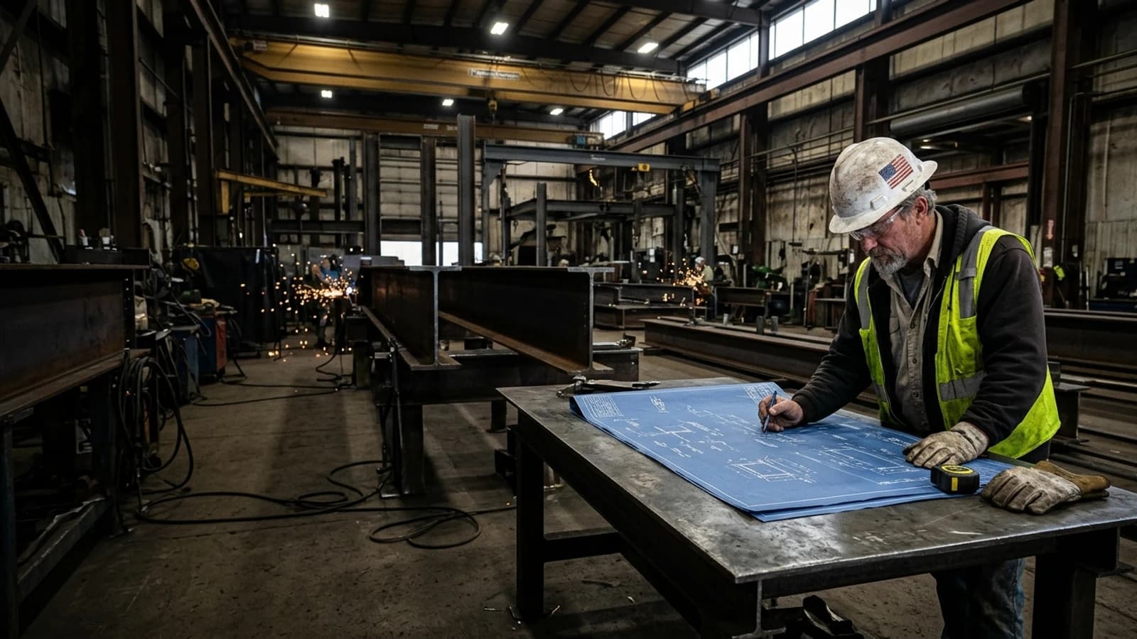
Detailed and accurate shop drawings to support fabrication, erection and project coordination. We provide beam and column assembly drawings, connection details, plate fabrication sheets, material lists and more for steel fabricators, contractors and erectors across the USA.
Turning Design Drawings into Fabrication-Ready Documents
Structural steel shop drawings provide detailed fabrication information based on the approved design drawings. They include member sizes, piece marks, connection details, dimensions, hole locations, material specifications and assembly instructions used in the fabrication shop and at the project site.
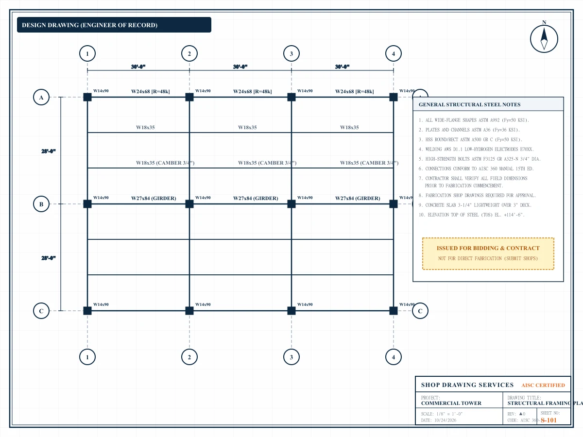
Learn More About Our ProcessDesign Drawing
(General Arrangement)
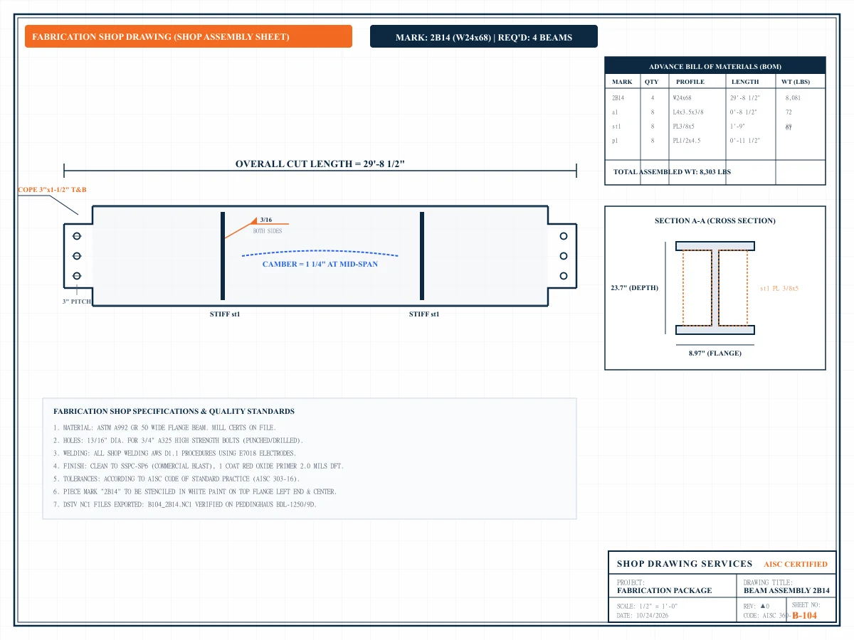
Shop Drawing
(Detailed Fabrication Sheet)
What's Included in Our Structural Steel Shop Drawings
We provide comprehensive fabrication documentation tailored to your project requirements.
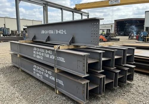
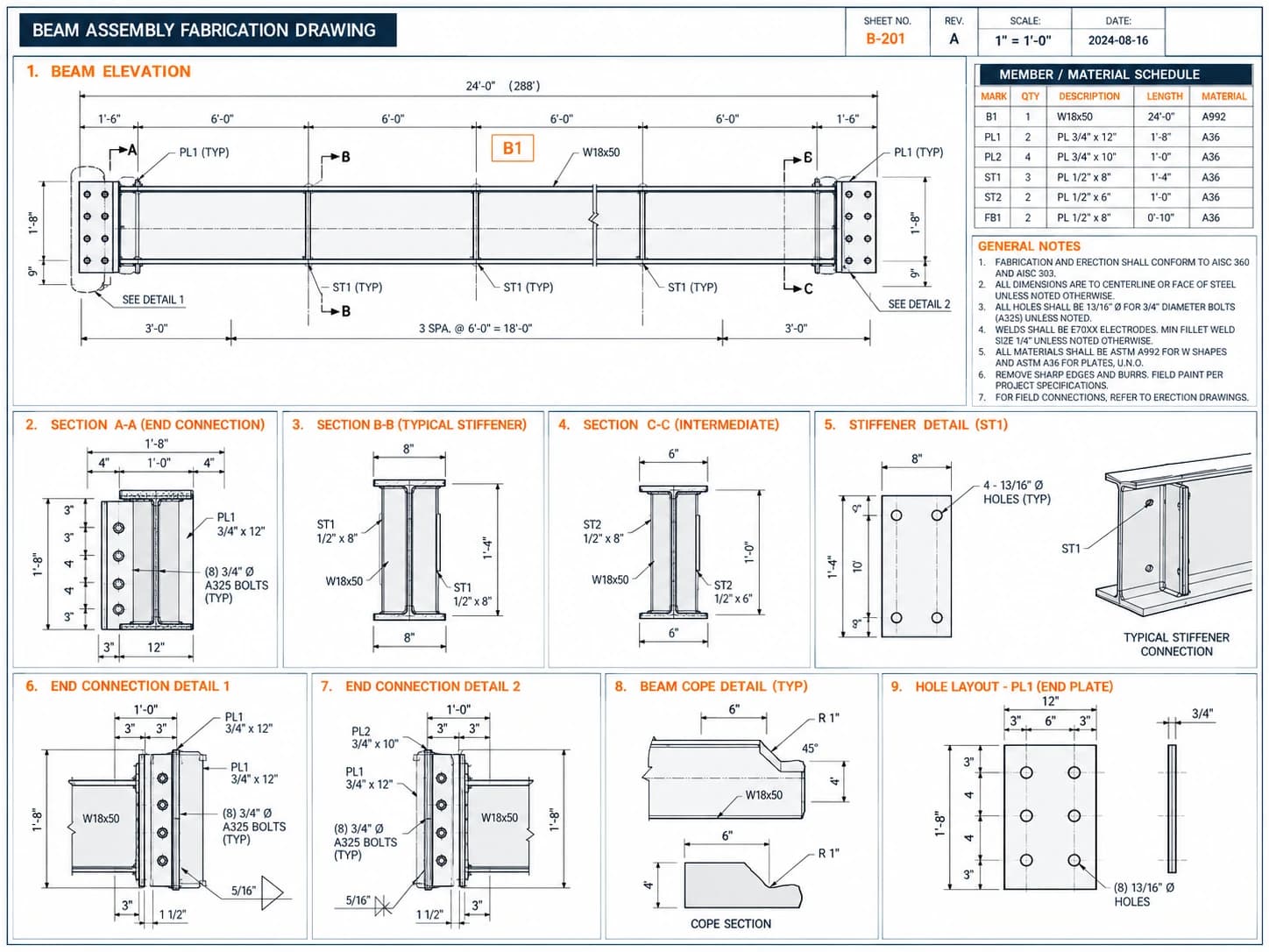
Detailed Beam Fabrication Drawings
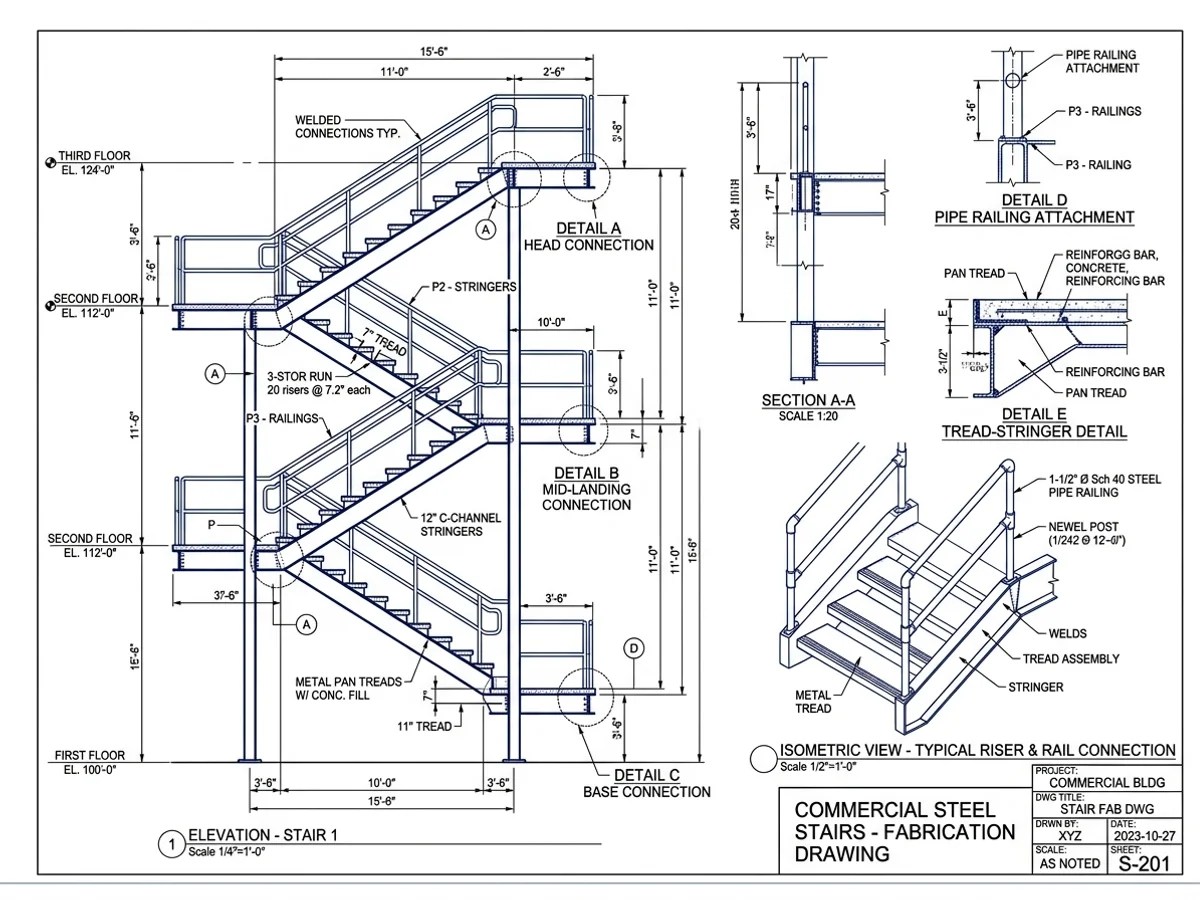
Our beam shop drawings include exact cut lengths, coping details, hole patterns, stiffeners, camber, material grade, piece marks and connection references to ensure smooth fabrication and on-site installation.
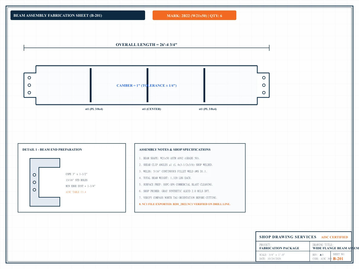
Beam Assembly Drawing (Sheet B-201)
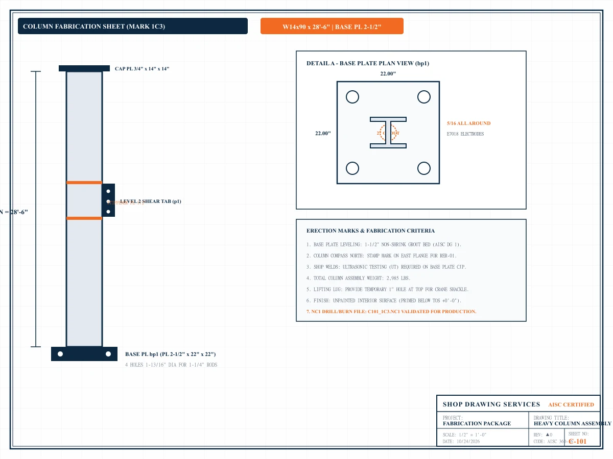
Column Assembly Drawing (Sheet C-101)
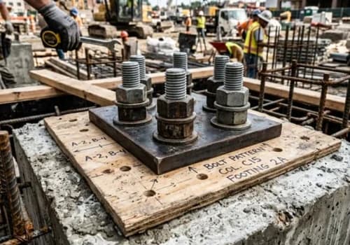
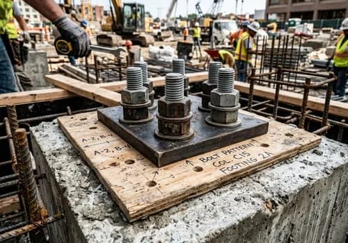
Column Assembly and Base Plate Details
Our column shop drawings cover complete assembly details with base plates, cap plates, splice locations, stiffeners and anchor information. Each drawing includes precise dimensions and fabrication notes for shop and field work.
Accurate Connection Details for Fabrication
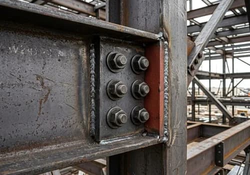
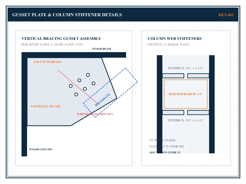
We provide detailed connection drawings such as shear tabs, end plates, gusset plates, base plates and bolted splices with clear dimensions, bolt-hole information and weld callouts based on the approved design documents.
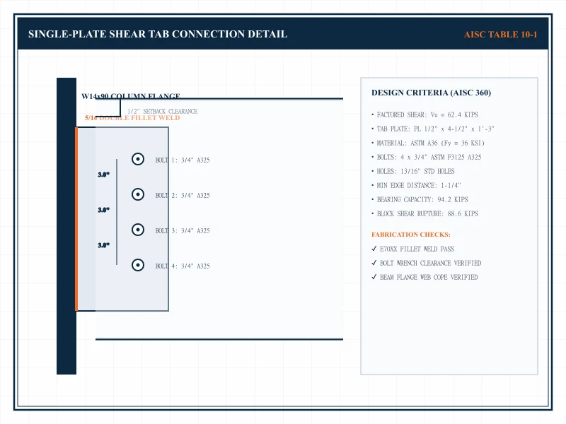
Shear Tab Connection
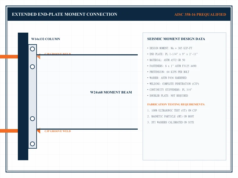
End Plate Connection
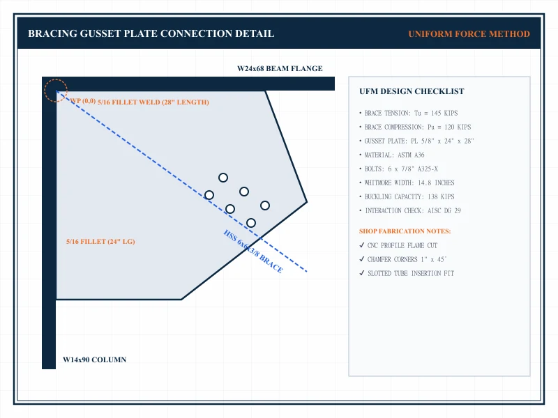
Gusset Plate Connection
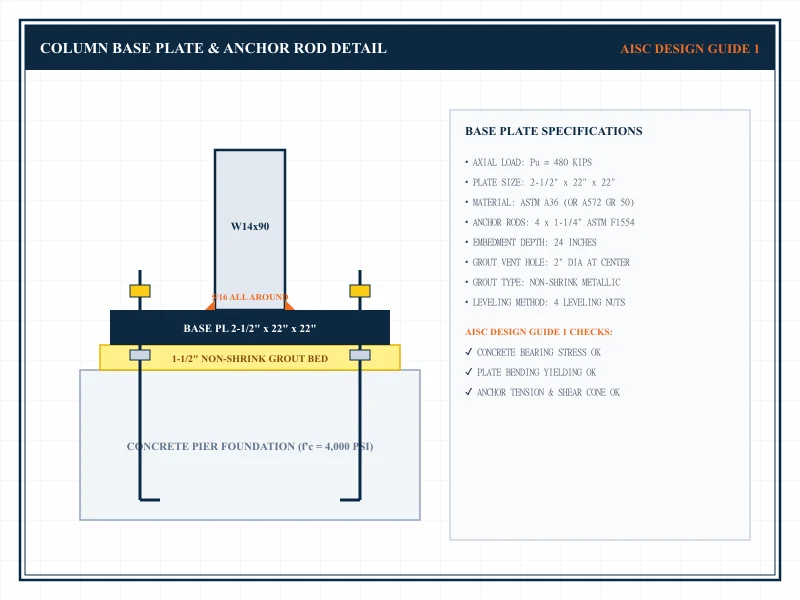
Base Plate Detail
Structural Steel Drawing Examples
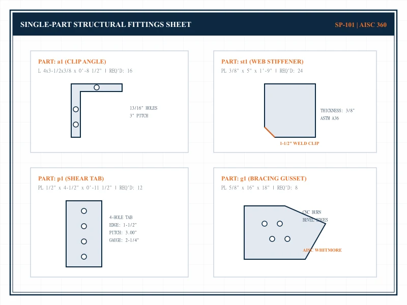
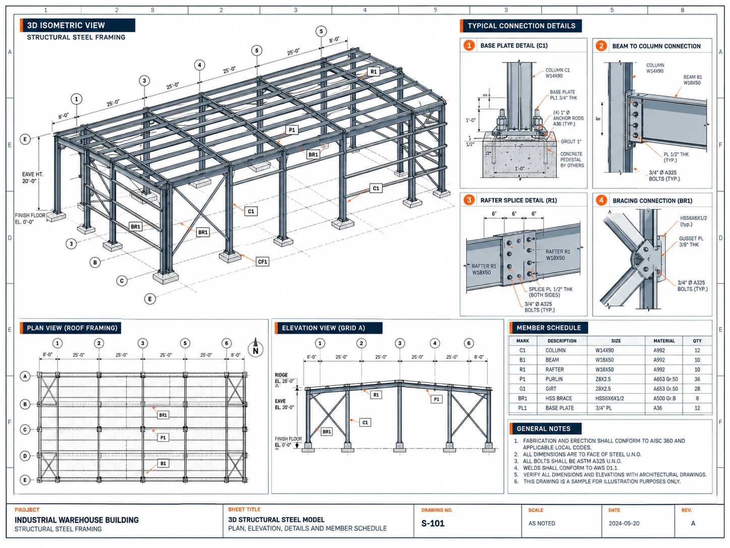
Explore examples of our fabrication drawing sheets including framing plans, 3D models, beam and column assemblies, bracing details, single-part sheets, and connection schedules.
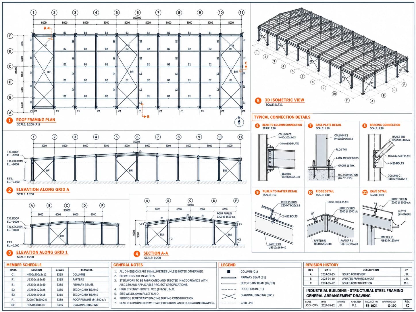
Structural Steel Framing Plan
Complete industrial building general arrangement framing sheet illustrating roof framing plans along Grids 1 through 11, longitudinal and transverse frame elevations, member schedules for primary and secondary beams, diagonal bracing callouts, and typical connection details.
Key Differences
| Feature | Shop Drawings | Erection Drawings |
|---|---|---|
| Purpose | Fabrication details | On-site installation |
| Audience | Fabricators | Erectors / Field Teams |
| Level of Detail | High (shop fabrication) | General (assembly & location) |
| Information | Exact dimensions, holes, welds | Member locations, elevations |
| Approval | Reviewed by EOR / Contractor | Issued for erection |
| Typical Output | Assembly & single-part sheets | Framing plans & erection details |
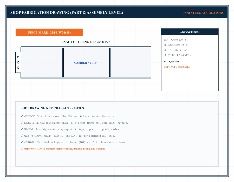
Shop Drawing
(Fabrication Detailing)
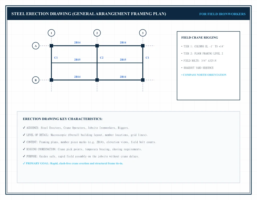
Erection Drawing
(Field Installation)
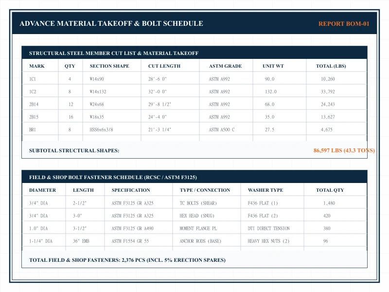
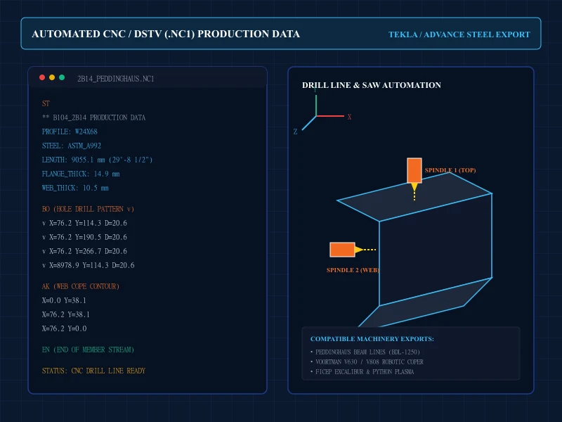
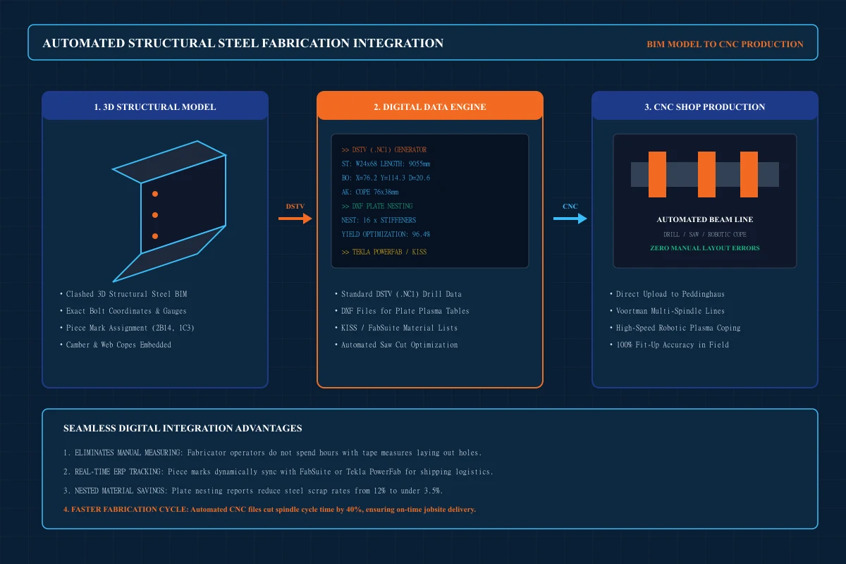
Material Lists, BOMs & CNC Machine Data
Modern American steel fabrication relies on automated CNC machinery and computer-integrated manufacturing. Our detailing workflow directly bridges the 3D model with your automated cutting and drilling equipment.
Every drawing package includes an advance Bill of Materials (BOM) detailing total project weights, lineal footage, and plate summaries. When planning steel budgets, preconstruction procurement, or comprehensive material takeoffs, fabricators and general contractors frequently pair these reports with professional construction cost estimating services to lock in mill pricing and secure dependable preconstruction quantity benchmarks before rolling schedules close.
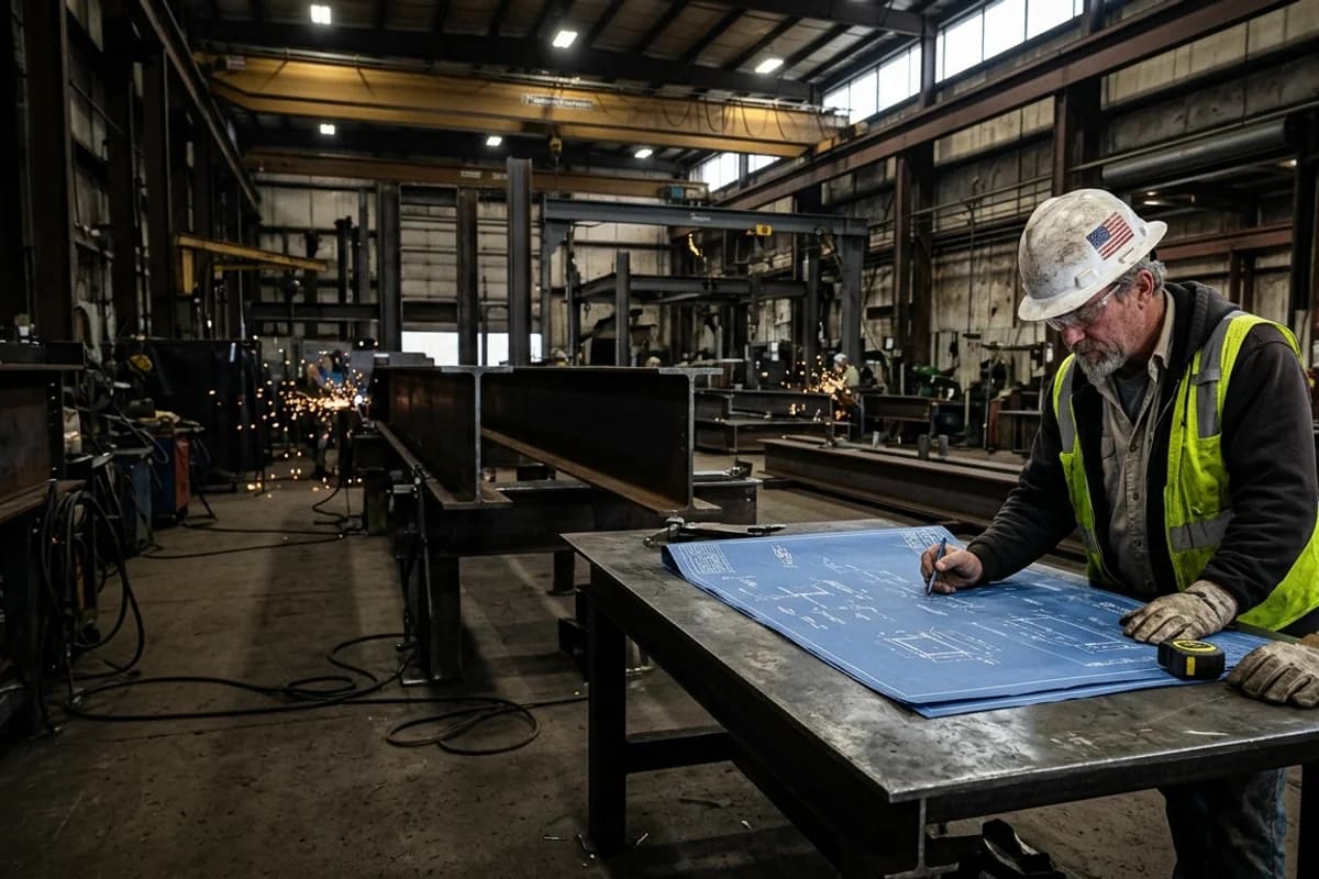

Project Kickoff Requirements
Complete contract documents ensure zero project onboarding delays.
Required Project Inputs to Begin Detailing
To guarantee on-time submittal releases without unnecessary RFI cycles, we conduct an audit of project documentation during the kickoff phase.
Structural Contract Drawings (S-Sheets)
Latest architectural/structural issued-for-construction (IFC) plans, framing elevations, sections, and general notes.
Architectural Drawings (A-Sheets)
Exterior wall assemblies, roof parapets, finish floor elevations, and stair/elevator shaft clearances.
Project Specifications (Section 05 12 00)
AISC steel grade requirements, bolt grades (A325/A490), shop primer specs, galvanizing callouts, and NDT criteria.
Connection Design Criteria & Loads
Reaction tables (shear, moment, axial tension/compression) or pre-engineered connection calculation reports.
Our Shop Drawing Preparation Process
From contract document intake to final fabrication release, every shop drawing package passes through a 5-stage production protocol.
Intake & Audit
Cross-reference S-sheets, specs, and addenda. Initial RFIs generated for ambiguities.
3D BIM Model
Millimeter-accurate 3D model defining gridlines, levels, slopes, sizes, and orientation.
Connection Details
Shear clips, moment welds, bracing gussets, and stiffeners complying with AISC 360.
QA Checking
Senior steel checker audits dimensions, bolt tool clearances, and piece marks.
Submittal Release
Issue vector PDFs, DWGs, BOM Excel schedules, and CNC DSTV files for fabrication.
Common Steel Drawing Errors & How We Eliminate Them
Fabrication mistakes and crane delays stem almost exclusively from drawing discrepancies. Here is how our detailing protocol prevents costly errors.
| Common Drawing Error | Potential Jobsite & Shop Impact | Our Prevention Protocol |
|---|---|---|
Inconsistent Piece Marks or Duplicate Member Tags | Causes wrong steel members to be shipped to jobsites, creating severe crane delays and sorting confusion in the field. | Automated piece marking engine with algorithmic uniqueness validation across all assemblies and single-part schedules. |
Inadequate Bolt Hole Edge Distances or Flange Clearances | Field bolts cannot be installed due to physical socket interference with beam webs, or violate AISC 360 minimum edge distance rules. | 3D virtual bolt wrench clearance simulation and automated AISC Table J3.4 / J3.5 minimum edge distance rule-checks. |
Ambiguous or Incomplete AWS Weld Callouts | Shop welders deposit wrong fillet throat thickness or omit required backing bars on CJP welds, resulting in failed ultrasonic weld tests. | Full AWS D1.1 standard welding symbols applied with explicit tail notations, effective throat callouts, and NDT requirements. |
Reversed Column Orientation or Disregarded Compass North | Columns erected 180 degrees backwards, placing beam connection tabs on the wrong framing grid and halting multi-story erection. | Prominent Project North arrow orientation callouts and distinct asymmetric column face tagging stamped on all drawings. |
Fabrication Off Superseded Revision Drawings | Fabricators cut steel to outdated structural plans, ignoring architectural addenda and generating thousands in scrapped steel. | Rigid delta revision clouding (▲1, ▲2), drawing release change logs, and explicit superseded watermark stamps on all releases. |
Missing or Uncoordinated Beam Camber Information | Beams fabricated flat sag under concrete floor deck pour, causing floor unevenness and triggering structural engineer pushback. | Clear camber callouts (e.g., 'CAMBER = 1 1/4" AT MID-SPAN') annotated directly in the title block and on elevation views. |
Multi-Tier Quality Control Before Submittal
We believe drawing verification should never be outsourced to the fabrication floor or the field ironworker. Our internal quality assurance procedure subjects every shop drawing to multi-tiered verification before release.
Model-to-Drawing Reconciliation
Automated audit confirming that every 2D drawing sheet matches the fully coordinated 3D BIM model without manual drafting overrides.
Bolt Gauge & Wrench Clearance Check
Verification of physical clearance envelopes for impact wrenches, torque multipliers, and tension calibrators per AISC Manual Table 7-15.
Senior Checker Sign-Off
Every deliverable package is reviewed by an experienced US steel detailing checker who validates weld notation, member tags, and tie-in dimensions.

100% Quality Audit
Every assembly, single part, and bolt schedule undergoes meticulous verification.
Applicable Standards & Detailing Responsibilities
We operate under the recognized codes governing the American steel construction industry, maintaining strict clarity between detailing documentation and licensed structural engineering design authority.
AISC 303-22
Code of Standard PracticeGoverns contractual relationships, drawing approval protocol, discrepancy resolution, and standard fabrication tolerances for steel buildings.
AISC 360-16 / 22
Structural Steel SpecificationDefines material criteria, member design capacities, connection geometry, minimum bolt spacing, edge distances, and shear tab limitations.
AWS D1.1 / D1.1M
Structural Welding CodeStandardizes welding symbols, weld throat calculations, prequalified joint details, backing bar callouts, and NDT notations.
RCSC Specification
High-Strength Bolted JointsRegulates ASTM F3125 Grade A325 and A490 bolt installation, washer requirements, standard vs slotted hole sizes, and joint pretensioning.
Who Needs Structural Steel Shop Drawings?
Our steel shop drawings bridge the gap between design engineering, shop manufacturing, and jobsite assembly.
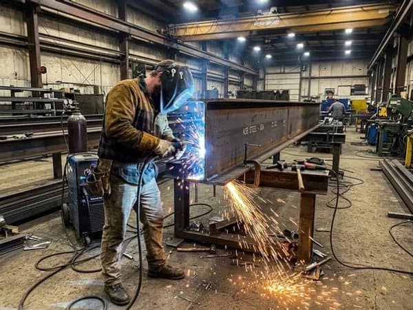
Steel Fabricators
We provide American structural steel fabricators with clean assembly drawings, single-part sheets, cut lists, and CNC NC1 files that keep beam lines and burn tables running at peak efficiency.
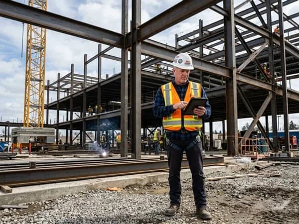
General Contractors
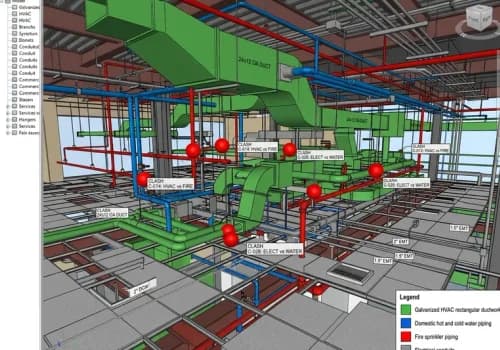
General contractors rely on our accurate shop drawing packages to coordinate trade handoffs, verify MEP clearances, avoid structural RFIs, and secure timely approvals from the design team.
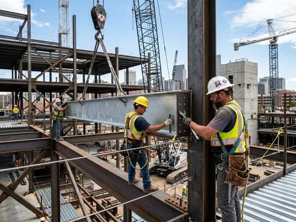
Steel Erectors & Riggers
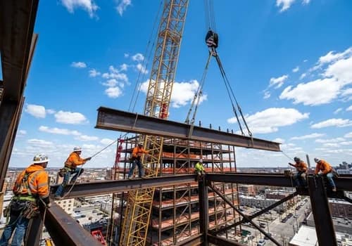
Field erectors benefit from clear general arrangements, sequential match marks, field bolt schedules, and crane rigging references that accelerate hook time and eliminate jobsite re-work.
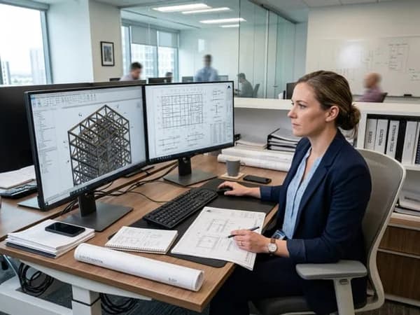
Steel Subcontractors
We handle secondary framing, stair towers, roof screen walls, canopies, and architectural steel packages, ensuring seamless fit-up against prime structural steel framing systems.
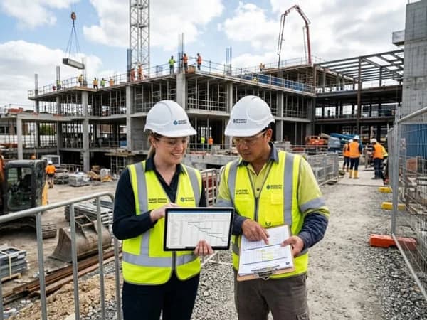
Procurement & Estimating
Preconstruction and purchasing managers leverage our advance bills of materials to order mill shapes early, lock in material pricing, and manage inventory without costly material overruns.
Looking for Dedicated GC Solutions?
Explore our comprehensive shop drawing services engineered specifically for American general contractors, CM firms, and design-build teams.
Structural Steel Project Types We Support
We prepare shop drawings across diverse commercial, industrial, and institutional sectors in the United States.

Commercial Office Buildings
Multi-story composite beam framing, moment frames, core bracing, elevator steel, and architectural exterior canopies.
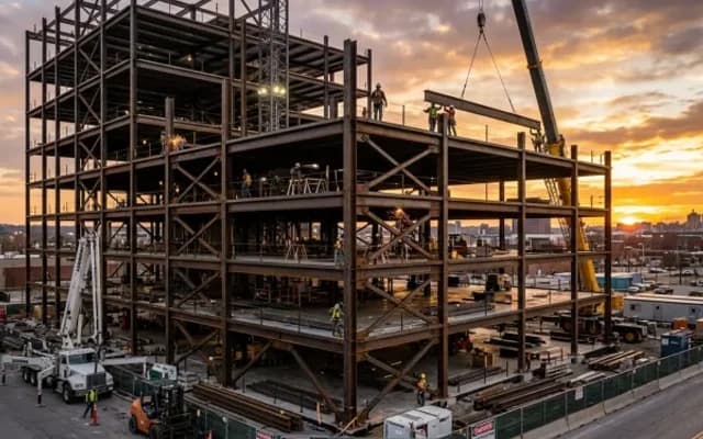
Industrial Logistics Warehouses
Long-span joist girder framing, interior column lines, tilt-up wall ledger coordination, and dock leveler pit steel packages.
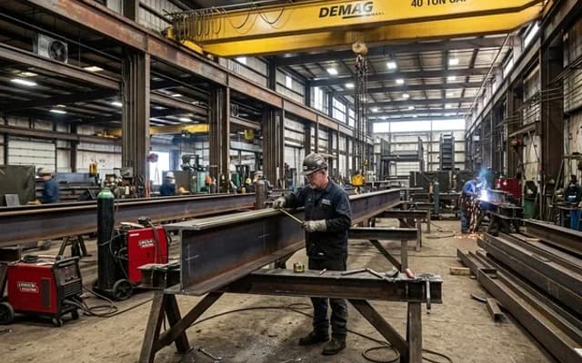
Manufacturing & Processing Facilities
Heavy crane runway girders, monorail beams, vibrating equipment support structures, and industrial catwalk networks.
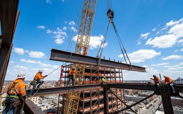
Structural Mezzanines & Platforms
Self-supporting equipment platforms, industrial storage mezzanines, access stairs, IBC-compliant handrails, and kickplates.
Building Expansions & Overbuilds
Tie-in connections to existing steel or masonry structures, field-verified survey integration, and structural retrofits.
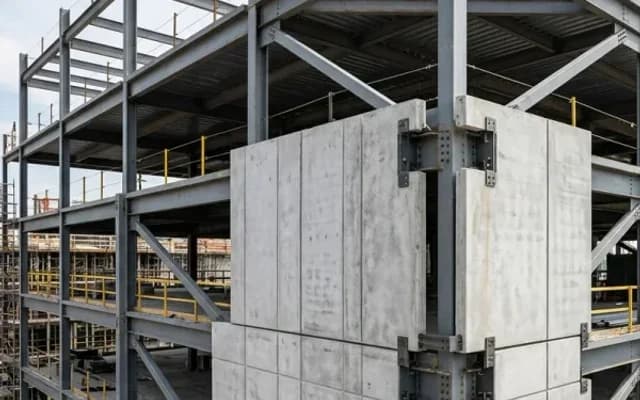
Institutional & Educational Facilities
School gymnasiums, university halls, hospital medical equipment framing, and architectural exposed structural steel (AESS).
Technical Guidance on Structural Steel Shop Drawings
Find clear answers to common questions regarding AISC 303 submittal review procedures, DSTV automated file exports, beam camber callouts, connection delegation, and turnaround schedules.
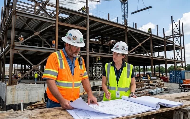
Have a Custom Technical Requirement?
Our detailing team is ready to review your project specifications and connection criteria.
Contact Our Technical TeamContract design drawings (S-sheets) prepared by the Structural Engineer of Record (EOR) establish member sizes, general framing layouts, design loads, and project performance specifications. Structural steel shop drawings, by contrast, are detailed manufacturing instructions created specifically for the steel fabricator. Shop drawings define the exact length to the 1/16th of an inch, individual piece marks (e.g., 2B14), flange copes, bolt hole coordinates, shop weld callouts, bevel angles, single-part fitting sheets, and CNC machine files required to fabricate each piece in the shop and erect it in the field.
Need Structural Steel Shop Drawings
for Your Next Project?
Send us your drawings and specifications for a detailed quote. We support fabricators, contractors and steel erectors across the USA.