

1. Welding Standards in Structural Detailing
Welding specifications are among the most rigorously inspected aspects of commercial structural steel fabrication. When shop drawings reach the structural engineer of record (EOR) or a certified third-party testing agency (CWI), improper weld symbols, ambiguous joint designations, or missing backing bar notes will trigger immediate submittal rejections.
Two primary standards govern structural welding on US building projects: AISC 360-22 (Chapter J) which dictates allowable stresses and connection geometry, and AWS D1.1:2025 which defines prequalified joint details, electrode classifications, and welding workmanship.
2. Fillet Welds vs. Groove Welds (CJP / PJP)
Shop detailers must accurately translate design shear and moment loads into proper weld types:
- Fillet Welds: Economical and simple to execute. The detailer must specify the effective throat thickness or leg size (e.g.
5/16,3/8). Per AISC 360 Table J2.4, minimum fillet weld sizes are governed by the thickness of the thicker part joined. - Complete Joint Penetration (CJP) Groove Welds: Required for full-moment connections where the weld metal must develop the full tensile strength of the connected member. Detailers must designate root openings, bevel angles (typically 45° to 60°), and backing bar extensions.
- Partial Joint Penetration (PJP) Groove Welds: Used when full joint strength is not required. Both groove preparation depth (S) and effective weld throat (E) must be clearly dimensioned (e.g.,
(1/2) 3/4).
3. AISC Weld Access Hole (Rat Hole) Geometries
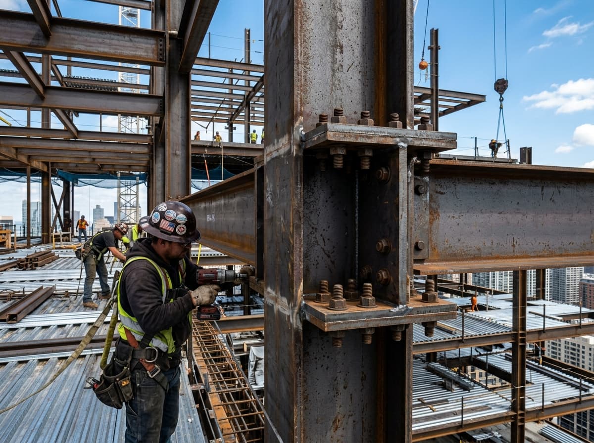
In moment connections where beam flanges are welded directly to column flanges using CJP groove welds, the web must be coped back to provide access for backing bars and weld torches. Under AISC 360 Section J1.6, weld access holes must satisfy specific geometry standards:
- Minimum length of 1.5 times the web thickness (or 1.5 inches minimum).
- Minimum height of the flange thickness plus 1/2 inch (minimum 3/4 inch).
- Smooth, fair radius transitions with no sharp notches to eliminate stress concentrations that cause brittle fracture during seismic events.
4. Reading and Specifying AWS A2.4 Weld Symbols
Shop drawing weld symbols must follow the standard AWS arrow, reference line, and tail syntax:
| Weld Symbol Component | Position on Reference Line | Standard Detailing Meaning |
|---|---|---|
| Arrow Side | Below the horizontal reference line | Weld is applied to the side of the joint where the arrow points. |
| Other Side | Above the horizontal reference line | Weld is applied to the opposite side of the joint. |
| Field Weld (Flag) | At the junction of arrow and reference line | Weld is to be performed by field ironworkers, NOT in the shop. |
| All-Around (Circle) | At the junction of arrow and reference line | Weld extends continuously 360° around the perimeter of the joint. |
| Tail Notation | Opposite the arrow head | Specifies welding process (e.g., FCAW-G, SMAW) or WPS reference. |
5. Detailing Checklist for 100% Weld Inspection Pass Rates
Before issuing shop drawings for approval, our quality control team runs through this mandatory verification checklist:
- Verify fillet weld sizes do not exceed the thickness of the thinner connected plate along rolled edges (AISC J2.2b).
- Check that weld length accounts for start/stop craters (or specify continuous welding).
- Confirm that all field groove welds have weld access holes compliant with AISC 360 J1.6.
- Ensure weld symbols include clear welding procedure specification (WPS) references in the tail when non-standard prequalified joints are used.