1. What Are Structural Steel Shop Drawings?
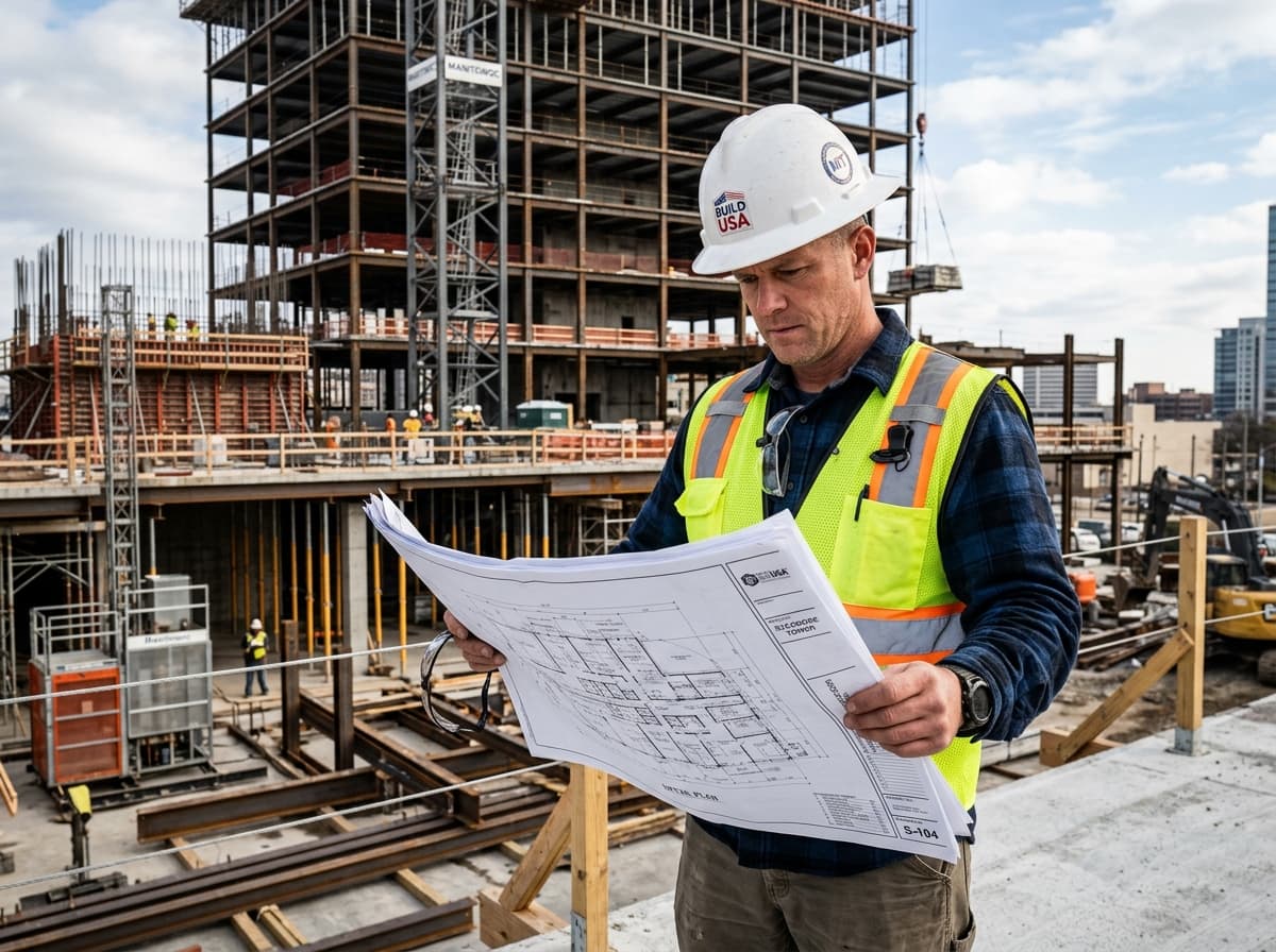
In American commercial construction, structural steel shop drawings serve as the legal and manufacturing bridge between the design team's contract documents (architectural and structural engineer-of-record drawings) and the physical fabrication shop floor. While structural engineering contract drawings specify general member sizes, geometry, and design loads, they purposefully do not provide the exact dimensions, hole locations, bevel preparations, or piece-mark numbering required to cut, drill, fit, and weld steel members in a shop.
Shop drawings translate design intent into precise manufacturing blueprints. Every single plate, clip angle, wide-flange beam, tube column, and moment connection is mathematically resolved to 1/16-inch tolerances or tighter.
2. Key Components of a Steel Shop Drawing Package
A full commercial steel detailing submittal package is comprised of three interdependent document types:
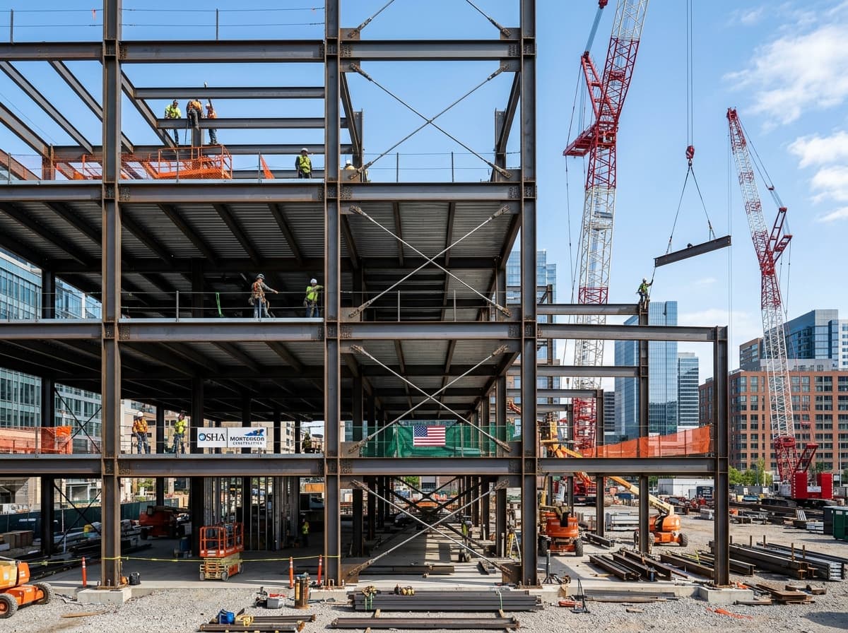
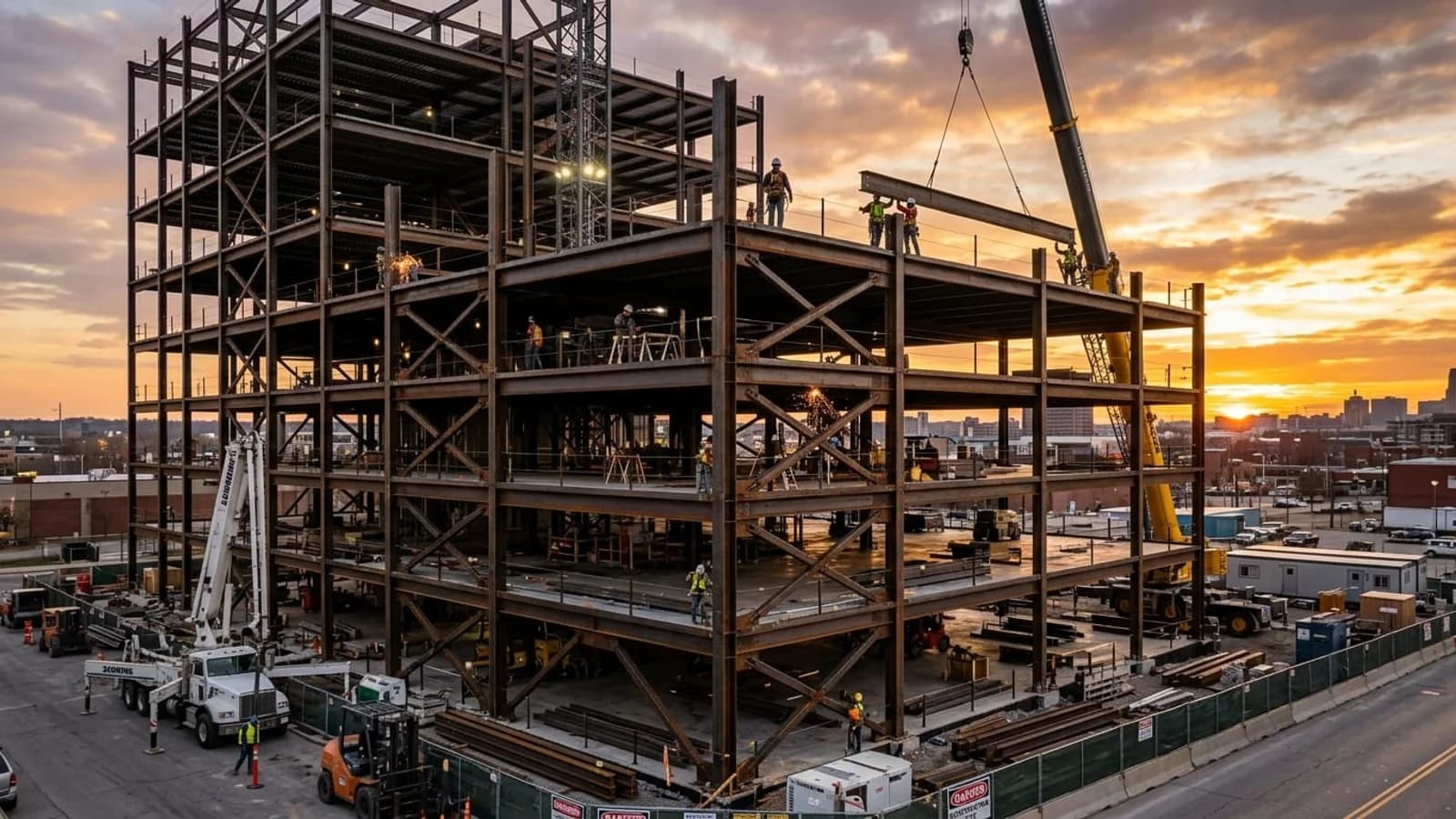
- Erection Plans (E-Sheets): Field placement drawings showing the spatial orientation, gridline coordinates, anchor bolt locations, and piece marks of all structural framing members. Used by the steel erector and crane crew on site.
- Assembly Drawings (Shop Sheets): Detailed drawings of fabricated shipping assemblies (e.g., a wide flange column with welded base plates, shear tabs, and cap plates attached). These sheets provide overall assembly dimensions, piece marks, paint requirements, and total shipping weights.
- Single-Part / Fitting Details: Individual dimensioned diagrams of detail pieces (shear tabs, stiffener plates, gussets, shims) manufactured before being tacked and welded onto main members.
3. AISC 303 & 360 Compliance Requirements
Every commercial shop drawing produced in the United States must strictly adhere to the guidelines published by the American Institute of Steel Construction (AISC). Specifically:
| AISC Standard | Application in Detailing | Critical Detailing Impact |
|---|---|---|
| AISC 303-22 | Code of Standard Practice | Defines standard fabrication tolerances, mill order variations, drawing review protocols, and classification of structural vs. misc steel. |
| AISC 360-22 | Specification for Structural Steel | Governs member capacities, bolt hole spacing (minimum 2-2/3d, preferred 3d), edge distances, and shear plane allowances. |
| AISC Steel Construction Manual 15th/16th Ed. | Standard Connection Tables | Standardized beam-to-column framed shear connections (double angles, single plates, end plates) with pre-engineered capacities. |
4. Piece Marking & Assembly Hierarchies
A systematic piece marking convention is essential to prevent costly erection errors. Under standard US detailing conventions:
- Shipping Assemblies are designated with capital letters denoting member type followed by an identification number (e.g.,
1B12for Floor 1 Beam 12, orC3for Column 3). - Detail Parts (fittings attached to shipping assemblies) are designated with lowercase letters followed by the parent mark (e.g.,
p1for plate 1,a2for clip angle 2). - Identical Parts receive identical marks across the entire project, allowing high-speed automated CNC cutting and punching without tracking individual parts.
5. Connection Detailing & Weld Callouts
Connections represent the highest risk and cost factor in structural steel fabrication. When detailing connections, detailers coordinate directly with connection design calculations provided by delegated engineers. Key detailing rules include:
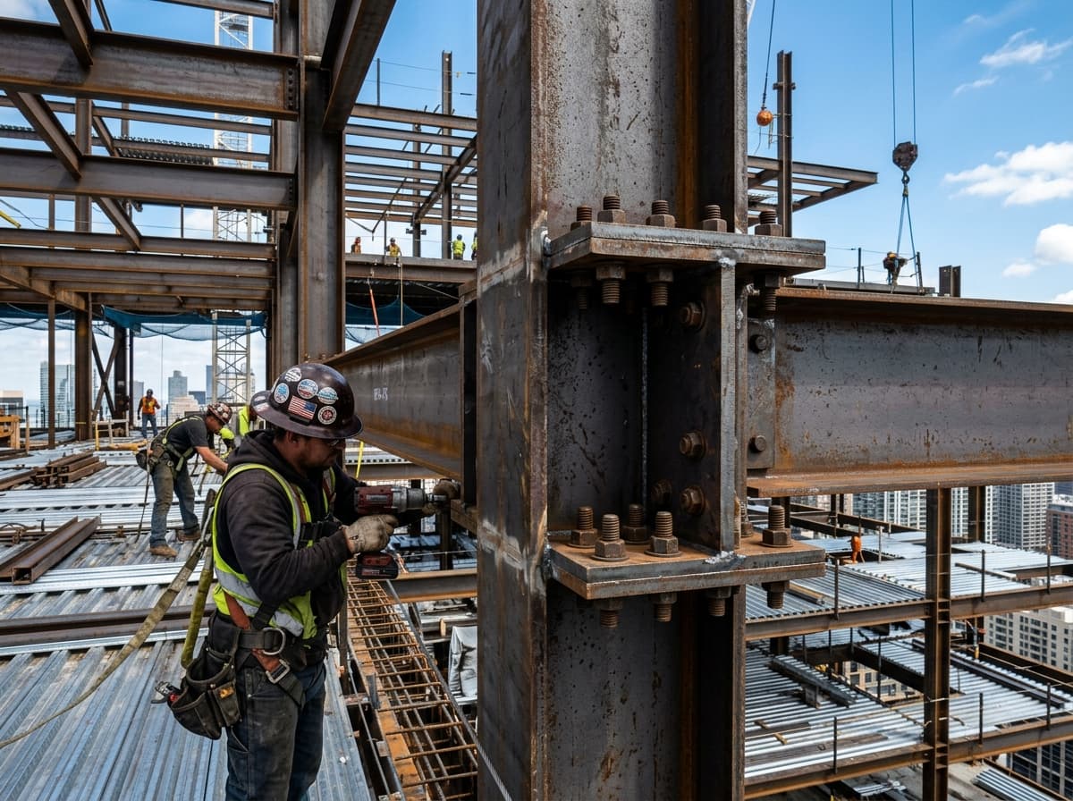
- Bolt Clearance: Ensure adequate clearance for pneumatic and electric impact wrenches. Maintain minimum 1-1/2" to 2" clearance from flanges for high-strength bolt tightening.
- Standard AWS Weld Symbols: Clearly differentiate between shop welds and field welds (flag symbol). Specify fillet weld leg sizes, complete joint penetration (CJP) bevel angles, and backing bar requirements according to AWS D1.1.
- Erection Clearances: Provide standard 1/16" to 1/8" setback tolerances at beam ends to ensure members slide easily between column flanges during field hoisting.
6. Preventing Costly Submittal Revisions & RFIs
Submittal rejections delay project critical paths and tie up fabrication capacity. The most common causes of "Revise and Resubmit" status on steel shop drawings are:
- Discrepancies Between Architectural and Structural Models: For example, perimeter steel elevations not accounting for exterior curtain wall pocket depths or architectural ceiling drops.
- Missing Weld Symbols or Non-Standard Symbols: Failing to specify effective throat thickness or welding process requirements.
- Anchor Bolt Layout Misalignment: Failing to cross-verify the foundation engineer's anchor bolt plans against the structural steel column baseplate details.
7. Key Takeaways for US General Contractors
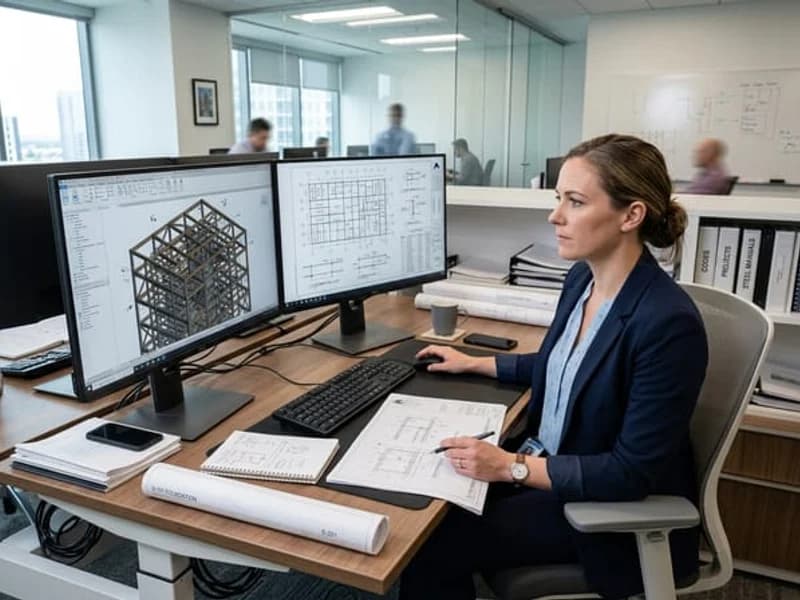
When selecting a detailing partner, general contractors should ensure the detailing team works directly in 3D BIM environments (Tekla Structures or SDS/2), generates fully populated DSTV / NC1 files for shop automated drill lines, and provides point cloud verification capabilities. A rigorous shop drawing package eliminates backcharges, reduces field welding, and ensures rapid engineer-of-record approval.