
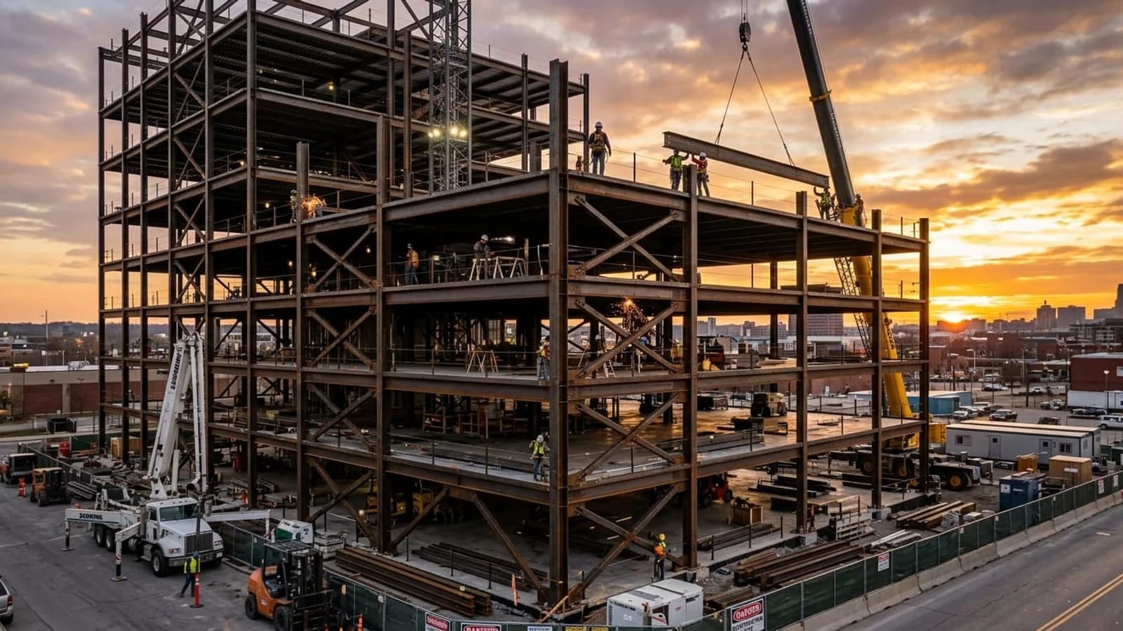
1. The Fundamental Distinction
While the terms "shop drawings" and "erection drawings" are often colloquially used interchangeably by non-specialists, in commercial structural steel practice they serve two completely distinct user groups, locations, and legal purposes:
- Shop Drawings: Used strictly inside the fabrication shop by welders, fitters, machine operators, and quality inspectors to manufacture individual pieces of steel.
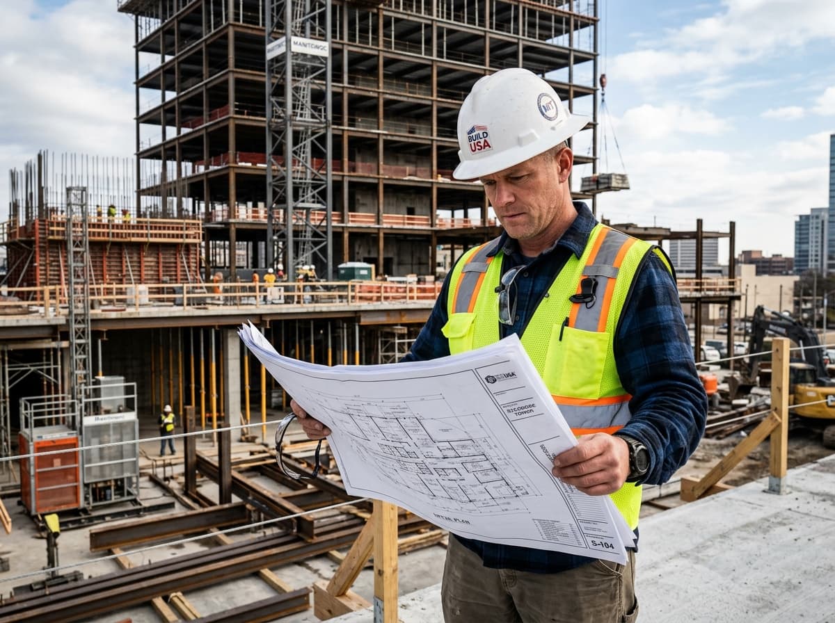
- Erection Drawings (E-Sheets): Used strictly on the construction job site by the general contractor, ironworkers, crane operators, and site surveyors to hoist, position, plumb, and permanently bolt or weld the framing together.
2. What Shop Drawings Contain
A structural shop drawing (assembly detail sheet) zooms in on a single manufactured member. It does not display the rest of the building. It provides:
- Exact Piece Marks: Mark numbers (e.g.
2B14) corresponding to the steel member being fabricated. - Exact Member Dimensions: Cut lengths, coping dimensions, flange notches, and bevel angles.
- Hole Coordinates: Centerline pitch, gage distances, slotted hole orientations, and edge distances to 1/16" accuracy.
- Attached Fittings: Shear tabs, moment connection stiffeners, doubler plates, and lifting lugs welded to the member before painting.
- Surface Treatment: Exact paint, primer, or hot-dip galvanizing specifications.
3. What Erection Drawings Contain
An erection drawing is an architectural-scale plan or elevation displaying the entire building framework. It provides:
- Gridline Positioning: Structural grid references (Column Lines A through G, 1 through 12).
- Member Piece Mark Callouts: Every piece mark placed next to its corresponding beam or column centerline so field crews know which piece goes where.
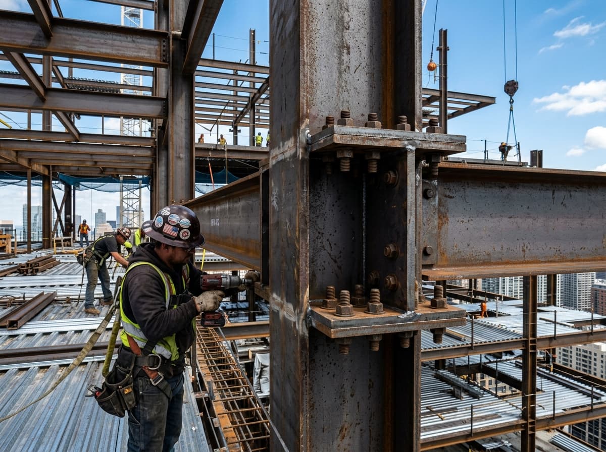
- Anchor Bolt Layouts: Coordinates, projections, baseplate orientations, and leveling nut elevations.
- Field Bolting Schedules: Bolt grades (ASTM A325, A490, F3125), quantities, diameters, and torque/tensioning specifications.
- Field Weld Symbols: Specific notes designating which connections are to be welded in the air after plumb-up.
4. Direct Side-by-Side Comparison
| Aspect | Structural Shop Drawings | Field Erection Drawings |
|---|---|---|
| Primary Audience | Shop Fabricators, Fitters, Welders, CNC Operators | Ironworkers, Field Superintendents, Crane Crews, Surveyors |
| Primary Location | Fabrication Facility Shop Floor | Job Site Field Trailer & Erection Crane Pad |
| Scale of Drawings | Large scale (1/2" = 1'-0" or 3/4" = 1'-0") | Architectural scale (1/8" = 1'-0" or 1/4" = 1'-0") |
| Information Scope | Single member with all attached shop fittings | Complete building floor framing, elevations, and grids |
| Hardware Included | Shop welded plates, stiffeners, clips, welds | Field bolts, anchor bolts, shim packs, field welds |
| Governing Standard | AISC 303 & 360, AWS D1.1 (Shop) | AISC 303, OSHA 29 CFR 1926 Subpart R (Field Safety) |
5. Legal, Safety, and OSHA Responsibilities
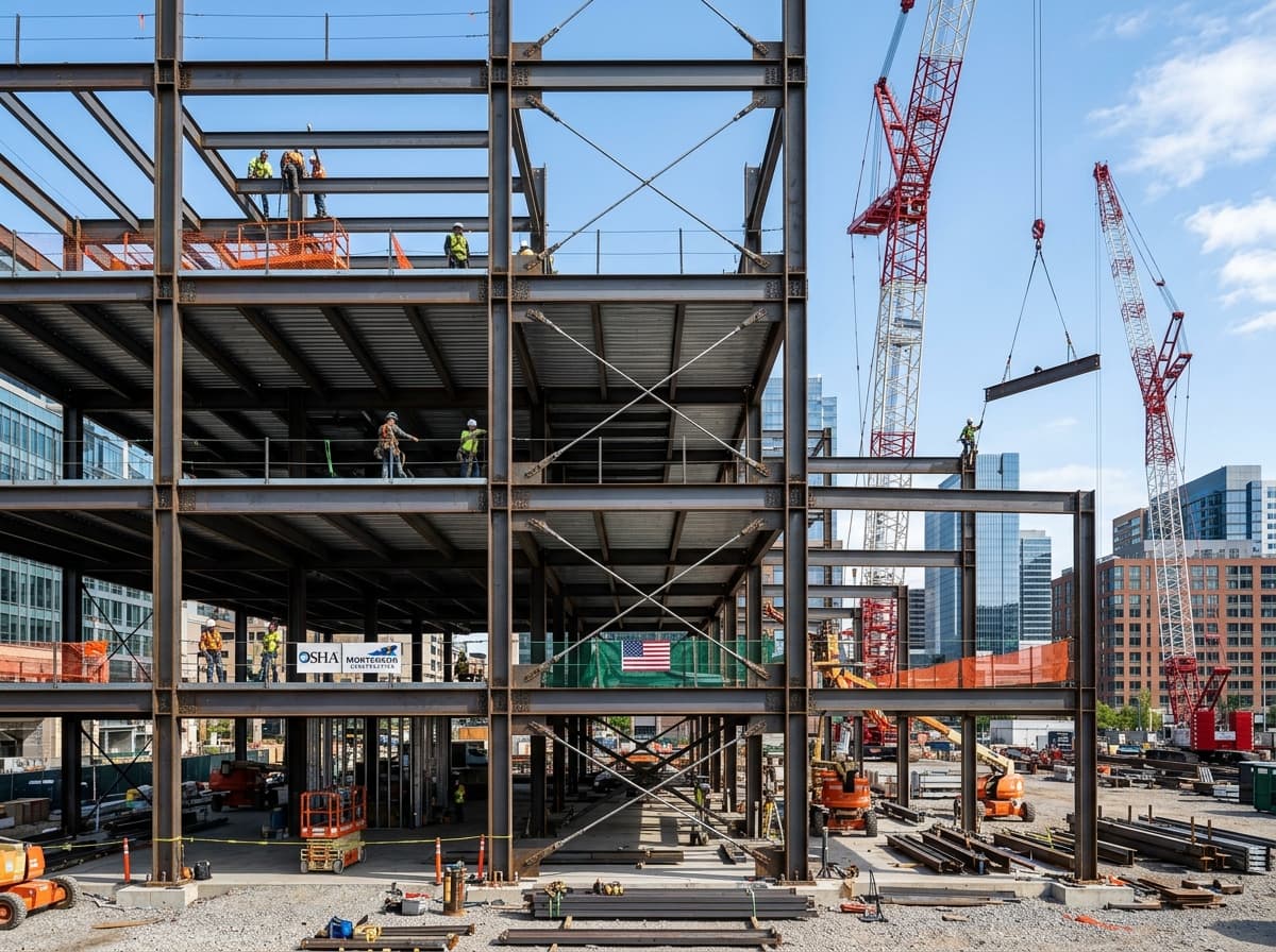
Under OSHA 1926.752 (Site Layout, Site-Specific Erection Plan and Construction Sequence), the steel erector must have approved erection plans on site before placing steel. Erection drawings must show:
- Column stability requirements and 4-anchor-bolt minimum OSHA rule for structural columns.
- Temporary erection bracing locations to prevent building collapse under wind loads before concrete slab placement.
- Perimeter safety cable attachment hole locations for fall protection.
6. How They Function Together in Modern BIM
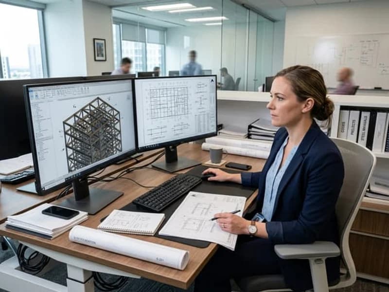
In modern 3D BIM detailing workflows using Tekla Structures, shop drawings and erection drawings are generated simultaneously from a unified, conflict-free 3D model. If a beam mark is changed on an erection plan, all associated shop fabrication sheets update automatically, guaranteeing 100% field alignment and zero misfits on site.