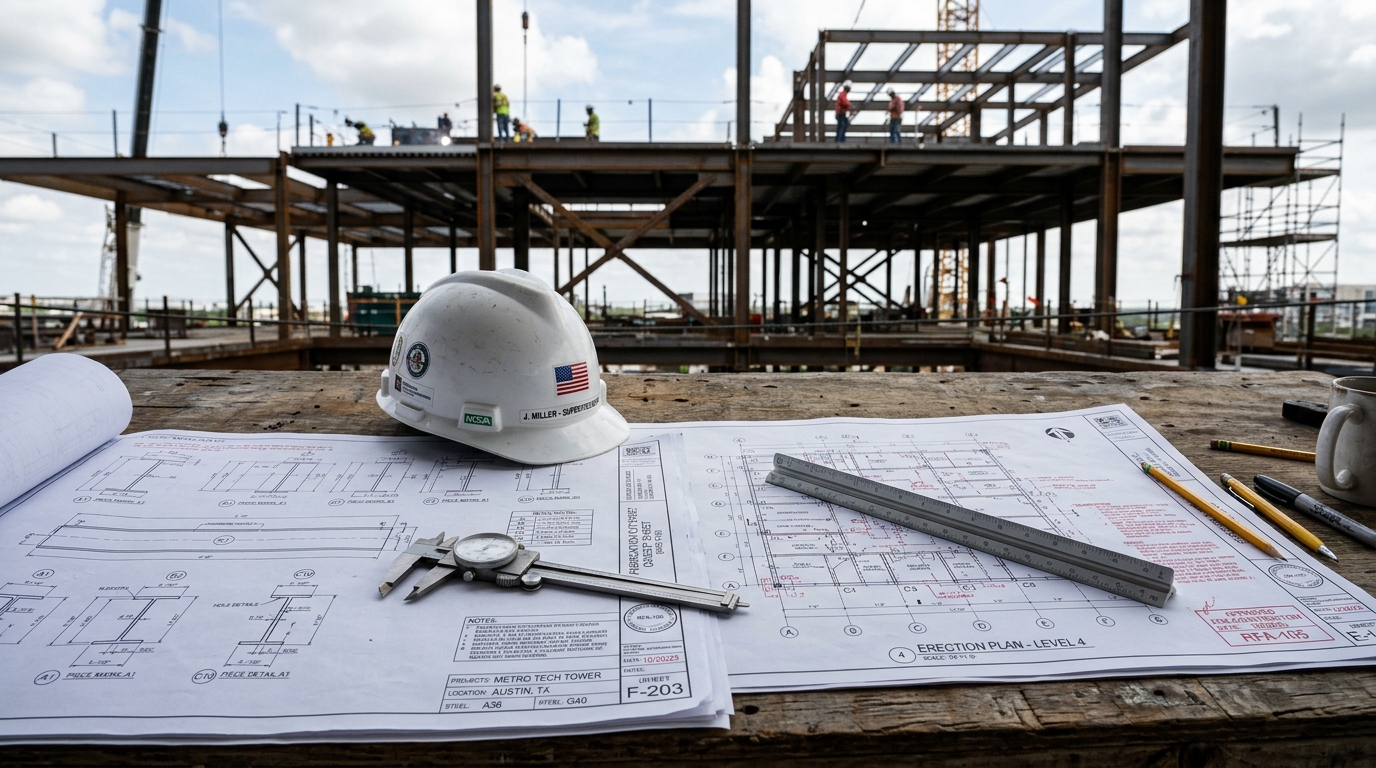

Why connection details come back
Short answer: Most connection returns are detailing omissions, not design disagreements. Show the reaction, state the joint type, dimension the full bolt layout, specify every weld completely, and read every view of the same connection before transmittal. Those five checks catch most first-review returns.
Most steel connection returns are not design disagreements. They are detailing omissions. A reaction never shown, a spacing or edge distance never dimensioned, a weld symbol missing its size or its shop or field side, or a joint type never stated. The reviewer cannot approve what is not on the drawing, so the package goes back even when the steel itself would have worked. That lost review cycle is the real cost: steel held from release, a shop schedule slipping, and a fabricator waiting on an answer that should have been on the sheet in the first place.
This guide covers the connection mistakes that reviewers catch first on US steel jobs: shear tabs, moment connections, bolt spacing and edge distance, unstated joint types, and three smaller returns that still stall a package. Each mistake is written the way a reviewer sees it: what is missing or wrong on the sheet, what the reviewer does with it, and the one check that catches it before transmittal. If you want the wider submittal picture first, our structural steel submittal checklist explains what the engineer of record checks before approval, and our structural steel detailing service covers the full detailing scope behind these checks.
Who this is for: steel fabricators, general contractors, project managers, and EOR reviewers checking a steel connection package before first review.
Mistake 1: shear tabs with no reaction and ignored eccentricity
A single plate shear tab, sometimes called a fin plate, is a simple shear connection only if the design reaction is on the drawing and the tab is detailed for it. The classic return is a shear tab with no shear reaction shown, or a reaction copied from a different beam. The reviewer cannot check bolt count, tab thickness, or weld size against a load that is not there, so the detail goes back. Never guess a reaction. If the contract documents do not give it, send a request for information (RFI) before detailing that joint, and hold the joint pending the answer. Guessing turns a one day RFI into a full revision cycle later, when the shop has already cut steel to the wrong load.
Eccentricity is the second shear tab trap. The bolt group sits away from the supporting member web, so the connection carries shear plus the moment created by that eccentricity. A tab detailed for shear alone, with bolts sized for shear alone, will be returned. The eccentricity value depends on the tab geometry, so there is no single number to memorize; the check is to confirm that the eccentricity was considered and that the bolt group and weld were sized for the combined effect, not for shear alone.
A complete shear tab detail shows every item on this list: tab thickness and grade, bolt diameter, grade, and count, hole type (standard, oversized, or slotted, with slot direction where slotted), weld size and length to the supporting member, cope dimensions, and whether the tab is shop welded or field bolted. Missing any one of these is a return, not a comment. The reviewer has no basis to approve a tab whose weld length or hole type is left to the shop to decide.
Mistake 2: moment connections detailed as bigger shear connections
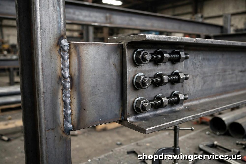
A moment connection is not a bigger shear connection. It must transfer flange tension and compression plus shear, so it has two load paths, and both must be detailed. Flange plates or direct flange welding carry the moment, while a web tab or web connection carries the shear. Detailing only the web, or only the flanges, is a return. The reviewer will ask for the missing path, and the shop cannot release the piece until it is shown.
Continuity plates and doubler plates are where moment details most often fall short. Where the column web or flange needs reinforcement for the flange forces, omitting the stiffener, its thickness, or its grade is a common return. If the contract documents do not call for reinforcement, do not invent it. If they do, show it completely, including welds to the column flange and web. A stiffener drawn in plan but missing in section, or shown without its welds, is the same problem in a different view: the shop cannot build what the drawing does not fully describe.
Weld specification is the other moment connection trap, governed in practice by AWS D1.1. A weld symbol that gives type but not size, or size but not length, forces a reviewer question. A groove weld that does not say complete joint penetration (CJP) or partial joint penetration (PJP) forces another. Weld access holes, backing bars, and backing bar removal where required must be shown, and every weld must be marked shop or field. Each missing item is a separate reason to return the detail.
One boundary matters here. For seismic moment frames, AISC 358 prequalified connections apply, and a non prequalified detail cannot simply be substituted. The examples in this article are gravity and wind moment connections, not seismic prequalified details. Presenting a generic moment detail as seismic qualified would be a design claim the detailer cannot make, and a reviewer will reject it on that ground alone.
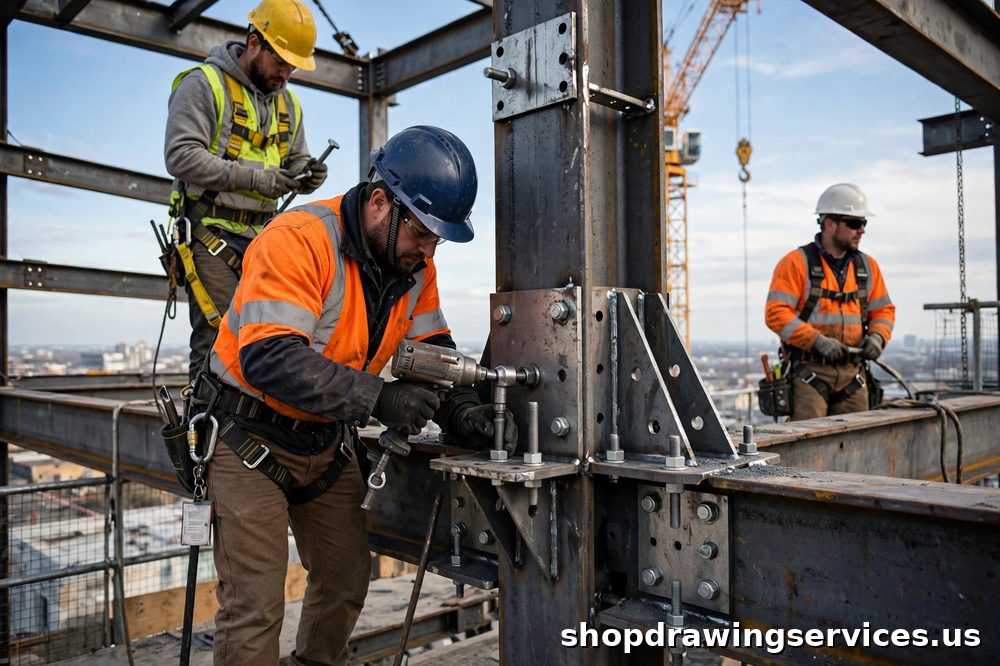
Mistake 3: bolt spacing and edge distance the reviewer checks first
Bolt layout is the fastest check a reviewer can make, which is why it is checked first. The limits below come from AISC 360 Chapter J: spacing in J3.3 and edge distance in J3.4, with the oversized hole increment in J3.5. They are detailing limits, not a substitute for a strength check. Bearing, tear out, block shear, and net section still govern, and the project specification and the adopted AISC edition govern over any summary table, including this one.
Bolt diameter | Minimum spacing (2 2/3d) | Preferred spacing (3d) | Minimum edge distance example |
|---|---|---|---|
3/4 in | 2 in | 2 1/4 in | 1 in (rolled edge, standard hole) |
1 in | 2 2/3 in | 3 in | 1 1/4 in (standard hole); 1 3/8 in (oversized hole in gusset) |
Two rules sit behind that table. Minimum centre to centre spacing is 2 2/3 times the nominal bolt diameter, with 3d preferred where practical, and the minimum clear distance between adjacent holes is not less than one bolt diameter. Minimum edge distance comes from AISC Table J3.4 by bolt diameter and edge type, and oversized or slotted holes add the Table J3.5 increment. Never quote a spacing or edge distance without the bolt diameter and hole type beside it, because the same number is right for one bolt and wrong for the next.
Maximum spacing and edge distance matter too, for sealing, stitching, and corrosion control. AISC limits summarized in the sources for this article are 24t or 12 in for painted members and 14t or 7 in for unpainted weathering steel for spacing, and 12t or 6 in for edge distance, where t is the thickness of the thinner connected part. Treat these as limits to check, not targets to design to. Spacing a bolt group at the maximum to save a hole is not good detailing; it is a corrosion and stiffness problem waiting for the field.
The detailing mistakes behind the numbers are just as common as wrong numbers. Gauge lines omitted, edge distance dimensioned from the wrong edge, spacing shown on one view but not the section, staggered bolts dimensioned inconsistently, and a bolt group copied from a previous job onto a thinner plate where bearing and tear out no longer work. The fix is a bolt layout check on every connection: count, diameter, grade, pitch, gauge, edge and end distance, and hole type, all dimensioned on the same detail. Our shop drawing services hub lists the trades this check applies to, from structural steel to miscellaneous metals.
Mistake 4: the joint type never stated
A drawing that says only "high strength bolts" is incomplete. The Research Council on Structural Connections (RCSC) Specification for Structural Joints Using High Strength Bolts defines three joint types, and the engineer of record must identify the type in the contract documents. The detailer must then carry it onto the drawing, because the shop builds a different joint depending on which type is called for.
A snug tight joint brings the plies into firm contact, tightened by a few impacts of an impact wrench or the full effort of an ironworker with a spud wrench. It is permitted for most bearing joints. A pretensioned joint installs bolts to a specified minimum pretension, by turn of nut, calibrated wrench, twist off tension control, or direct tension indicator methods. Pretensioning is required where the specification or code requires it, for significant load reversal, fatigue, bolts in tension, and other RCSC cases. A slip critical joint is a pretensioned joint where slip must be prevented, with faying surfaces prepared to a calculable slip resistance: Class A clean mill scale, with a slip coefficient of 0.30, or Class B blast cleaned, with a coefficient of 0.50.
The mistake to name plainly is the mismatch: specifying slip critical bolts but detailing standard paint on the faying surface, or specifying snug tight bolts where the design assumed slip critical behavior. Either way the shop builds one joint and the design assumed another. Paint on a slip critical faying surface changes the friction the joint depends on, so the surface preparation and the surface class must be stated on the drawing, not left to the shop default paint system. If a joint is slip critical, say so, state the surface class, and mask or protect the faying surface accordingly.
Three more returns that still stall a package
First, inconsistent views. A connection shown as bearing in elevation but as shear in section, or a stiffener shown in plan but missing in section, tells the reviewer the set was never read as a whole. The fix is simple and often skipped: one checker reads every view of the same connection before transmittal.
Second, material grade omitted. A plate thickness shown without its grade means procurement cannot order and the reviewer cannot check. Every plate gets thickness and grade, for example ASTM A36 plates and A992 wide flange members where specified. Thickness alone is half a specification.
Third, coping, clearance, and erection fit never checked. Beam cope dimensions, bolt access for the impact wrench, and field weld access must be verified on the detail. A connection that cannot be bolted or welded in the position shown will come back from the shop or the field, not just from the reviewer, and by then steel may already be cut. If you are unsure how a connection set fits the wider package, compare it against the three drawing sets in our guide to shop drawings vs fabrication drawings vs erection drawings, so a shop detail is never mistaken for a field instruction.
Pre-transmittal connection checklist
Run this checklist on every connection before the package leaves the office. One unchecked box is one reason for a return.
Check | What to confirm |
|---|---|
Reaction shown | Shear, moment, or both, from the contract documents, never guessed |
Joint type stated | Snug tight, pretensioned, or slip critical, as specified by the engineer |
Bolt layout complete | Count, diameter, grade, pitch, gauge, edge and end distance, hole type |
Welds fully specified | Type, size, length, CJP or PJP where grooved, shop or field, access and backing |
Stiffeners complete | Thickness and grade, with welds to column flange and web |
Faying surface stated | Surface class where slip critical, and paint masking where required |
Views consistent | Same connection reads the same in plan, elevation, and section |
Cope and access checked | Cope dimensions, wrench access, and field weld access verified |
RFI template: when the reaction is missing
When a connection reaction is missing from the contract documents, do not detail around it. Send one short RFI and hold that joint. Use this format:
Location: gridline and level, with beam and column piece marks. Missing information: shear reaction, moment, or both, and which load combination governs if stated. Held pending answer: the named connection detail and any members whose release depends on it. Question: please confirm the design shear and moment for this connection, or direct us to the contract document where they are given. One clear question gets a faster answer than a paragraph of background, and it creates the record the shop needs if the schedule moves.
Frequently asked questions
Can a shear tab be detailed without a design reaction?
No. Without the reaction, bolt count, tab thickness, and weld size cannot be checked. RFI the missing reaction and hold the joint.
Is a moment connection just a shear connection with more bolts?
No. A moment connection transfers flange forces plus shear, so it needs both a flange load path and a web load path, detailed separately.
What is the minimum bolt spacing in AISC 360?
Minimum centre to centre spacing is 2 2/3 times the bolt diameter, with 3d preferred. For a 3/4 in bolt that is 2 in minimum and 2 1/4 in preferred; for a 1 in bolt, 2 2/3 in minimum.
When must a joint be slip critical?
When the engineer of record designates it as such in the contract documents, including cases such as fatigue with load reversal, oversized or slotted holes, or where slip would harm the structure. The detailer carries that designation onto the drawing with the faying surface class.
Get the connection right before the first review
Connection returns rarely mean the steel was wrong. They mean the drawing left the reviewer no way to approve it. Show the reaction, state the joint type, dimension the full bolt layout, specify every weld completely, and read every view of the same connection before transmittal. Those five habits catch most of the returns in this guide, and they cost minutes in the office against weeks on a held release. To discuss a steel package or to request a sample connection sheet to your standards, contact our detailing team with your scope and timeline.
What to send for a connection review: the IFC set, contract documents, design reactions, joint types, and any prior review comments. What you receive back is a checked connection set with a revision log covering every set holder, so the shop and field work from the same revision.
Sources and standards referenced: AISC 360 Specification for Structural Steel Buildings, Chapter J (spacing J3.3, edge distance Table J3.4, oversized hole increment J3.5); RCSC Specification for Structural Joints Using High Strength Bolts (June 5, 2025 edition); AWS D1.1 Structural Welding Code, Steel; AISC 358 Prequalified Connections for Special and Intermediate Steel Moment Frames. Always verify against the project specification and the code edition adopted for your project.