New plants and production bays
Lay out framing grids, crane or equipment interfaces, and erection sequence using the current structural package. Cross-reference member marks, anchor details and the fabricator’s release list.
For U.S. plant contractors and fabricators
Detail steel, access platforms, equipment supports, piping and ductwork for plant builds, production line expansions and shutdown retrofits. Organize the drawings around verified site conditions and the fabrication sequence.

Project types
The drawing package depends on what is being installed, what is already in the plant and when the crew can get to it. Define those conditions early so the shop knows which assemblies can move into fabrication.
Lay out framing grids, crane or equipment interfaces, and erection sequence using the current structural package. Cross-reference member marks, anchor details and the fabricator’s release list.
Show where new conveyors, equipment frames or platforms meet existing steel and concrete. Tie the new work to verified datums and identify which dimensions are still open.
Identify the assemblies affected by shutdown limits, restricted access and tie-in windows. Coordinate shop breaks and field connections with the installation plan.
Trade packages
Start with one trade or define a coordinated package. We agree on drawing references, deliverables and the boundary between the design team, equipment supplier and shop.
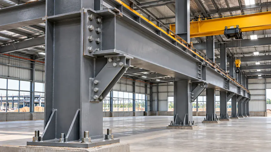
Assembly and part drawings, member marks, specified connection details and erection plans for plant framing and expansions.
Explore Structural steel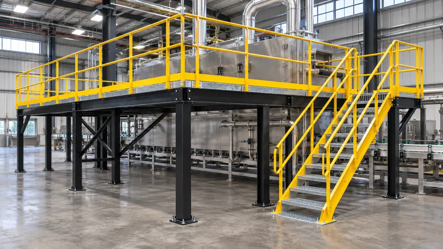
Platform framing, grating panels, stairs, guards and access openings coordinated around approved equipment and service clearances.
Explore Access platforms and catwalks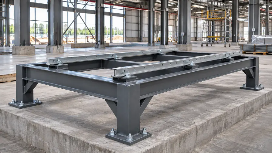
Base frames, support brackets and anchor layouts using approved equipment footprints, attachment criteria and loads supplied by the project team.
Explore Equipment support steel
Scoped piping layouts, spool details and tie-in references using the approved line list, routing, materials and support information.
Explore Mechanical piping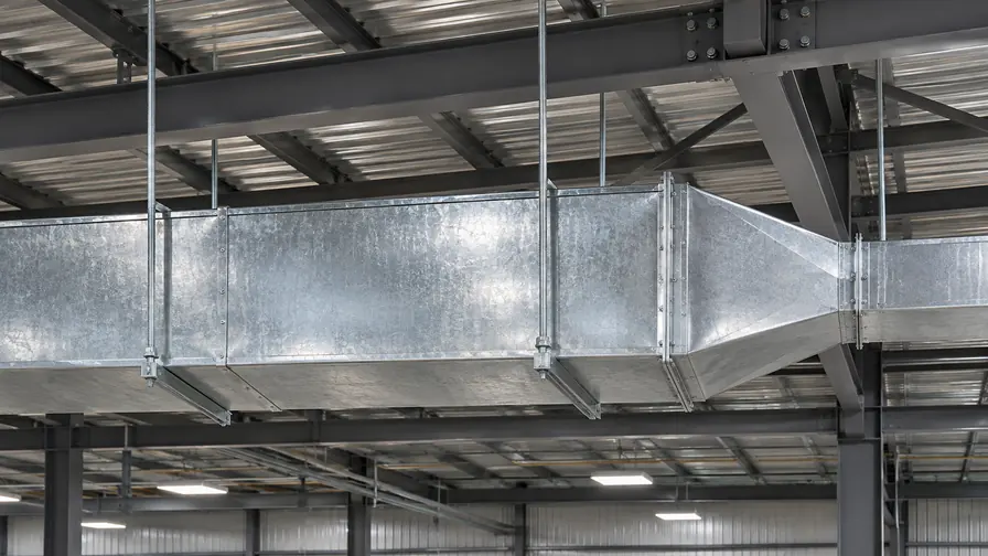
Dimensioned duct runs, transitions, hanger layouts and coordination sections around steelwork and equipment access.
Explore Industrial ductwork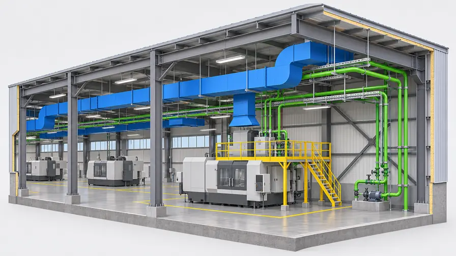
Model views and issue references for conflicts between supports, equipment, piping, ductwork and maintenance zones.
Explore BIM coordinationExisting facility coordination
A replacement line may cross existing steel and share a service aisle with operating equipment. Use the same field datum on the model, spool sheet and support details. Identify where measurements, access or operations decisions are still open.
Drawing samples
Open a steel framing, platform, equipment support, piping or ductwork sheet to inspect dimensions and references. These illustrative CAD-style sheets are marked “Not for Construction.”
Sheet 1 of 5
Review workflow
Set trade limits, drawing outputs and release dates. Identify the current design issue, equipment vendor files and the site dimensions the field team will provide.
Agree on shop and field breaks, installation access, shipping sizes and any assemblies needed early. Track outstanding questions against drawing or assembly marks.
Update the drawing register after review. Identify which steel, spools or duct assemblies can be released and which remain on hold for a verified tie-in.
Quote checklist
Send the latest references and identify what is verified in the field. Flag the items that need a drawing package before procurement, delivery or an outage.
FAQs
Retrofits, field information, fabrication releases and files.
Yes. Share the current plant drawings, verified dimensions or available scan data, and the agreed limits of work. We can identify where more field information is needed before affected details are released.
Yes. Provide the governing design, approved equipment data and support or attachment criteria. We can scope a single assembly or a group of assemblies by production area.
We can label the open dimensions and identify the drawings that depend on them. The affected items can stay on hold until the revised vendor or field information is confirmed.
We can organize approved packages by area or installation window. Send the outage dates, site constraints and review milestones so the drawing schedule accounts for them.
PDF review sets are common. Specify any DWG, native model, material lists, part reports or machine files when requesting a quote so the scope reflects the shop’s workflow.
The responsible project engineer and approved equipment suppliers provide the governing design information. We detail the agreed scope against those references and flag gaps for the project team.
Share the design files, trade scope and first required release. We’ll confirm the drawing package and quote it for your project.