Steel Platform & Catwalk Drawings for Fabricators
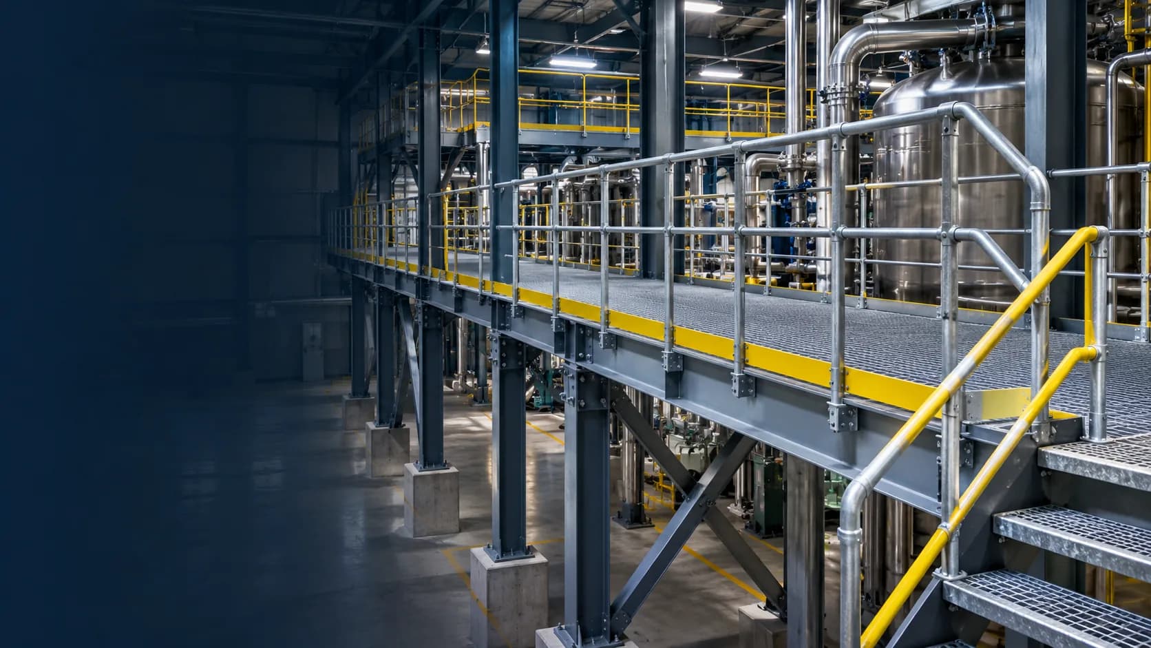
Industrial access platforms and catwalks need coordinated drawings for framing, grating, guardrails, connections and equipment clearances. We prepare scope-specific shop drawing packages to help US fabricators and contractors review and organize the steelwork needed for production and field installation.
Definition & Detailing Scope
What Are Steel Platform & Catwalk Shop Drawings?
Steel platform and catwalk shop drawings communicate how a specified access structure is arranged, broken into fabricated components, connected to its supporting structure and coordinated with nearby equipment. A drawing set often brings together layout plans, elevations, support framing, steel grating, edge protection, connection references and identifying part information.
A platform is generally a wider work or service area built to provide access around equipment, a vessel, a duct or an operating level. A catwalk is typically a narrower walkway that connects working locations or provides a route alongside plant equipment. The exact classification depends on project design and intended use.
The contract design establishes the required loads, structural behavior, performance criteria and system requirements. Detailing translates that information into coordinated shop and field reference documents within the contracted scope. Where an access path, guardrail termination, grating opening or connection is unresolved, the issue should be identified for clarification rather than filled in with invented design assumptions.
A practical example is an elevated platform around a large tank. The arrangement drawing identifies the access position and surrounding equipment. Framing sheets organize steel members and supports. Grating layouts show panel breaks and planned openings. Connection and interface sheets communicate the approved attachments and guardrail locations. Each drawing depends on the others being consistent.
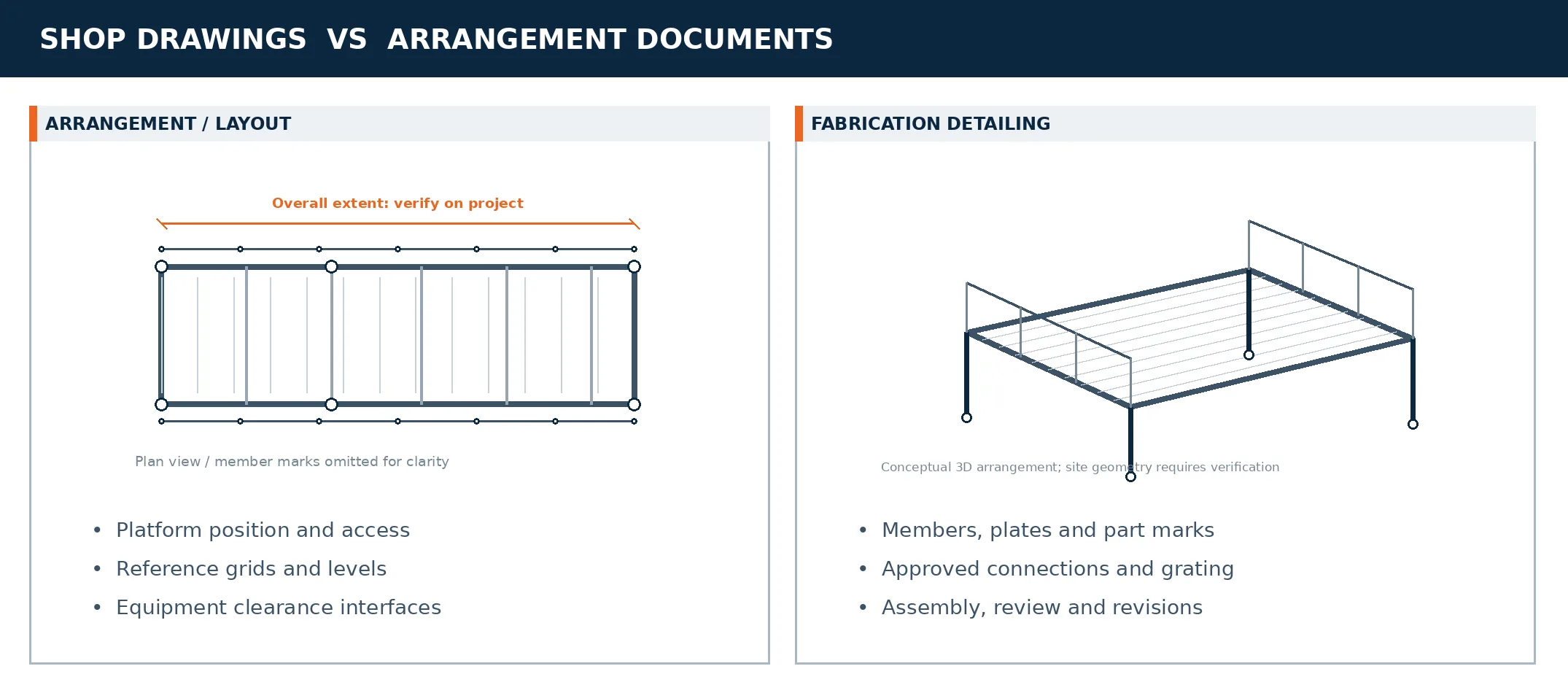
Design Intent vs. Shop Fabrication Documentation
Coordinating overall layout geometry with shop detailing sheets.
Assembly Types & Applications
Industrial Platforms, Catwalks & Access Structures We Detail
The detailing requirements for a compact maintenance platform differ from those for a long process-plant walkway. We prepare drawing packages around the specific layout, structural design information, fabrication method and interfaces identified in each project.
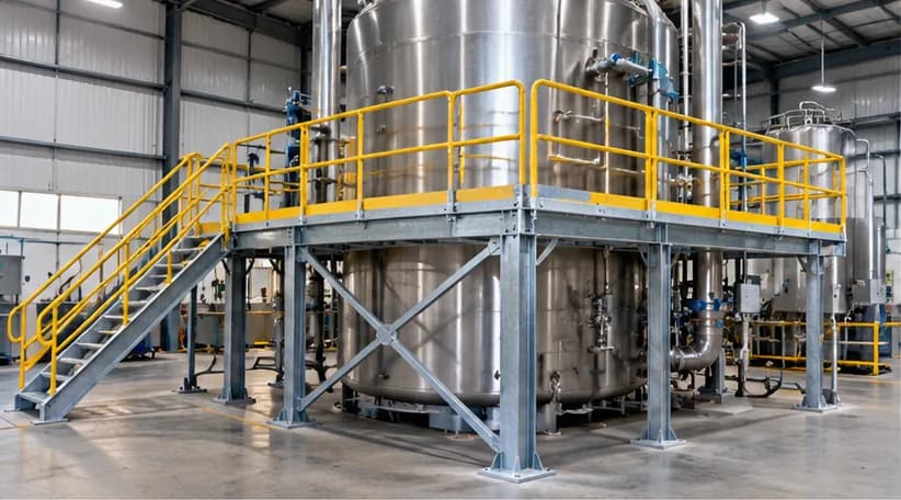
Tank and Vessel Access Platforms
Service platforms located around tank shells, inspection hatches and process equipment. Drawings must coordinate framing, edge protection, access routes and maintenance clearance with the approved plant arrangement.

Industrial Pipe-Rack Catwalks
Elevated walkways along pipelines and process racks. Shop documentation should reflect member placement, access width, support locations, crossing points and interfaces with nearby piping and cable routes.
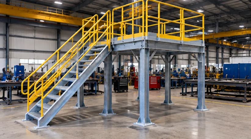
Freestanding Equipment Platforms
Independent access decks and service platforms with structural columns, bracing and stairs. Details organize the fabricator's assemblies and the approved connections to foundations or other supports.
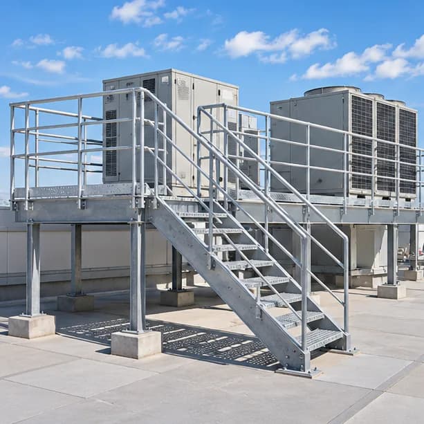
Rooftop Service Platforms
Access steelwork around HVAC units and rooftop maintenance areas. Relevant coordination includes access clearances, support conditions, roof-envelope penetrations where applicable and project-specified finish requirements.
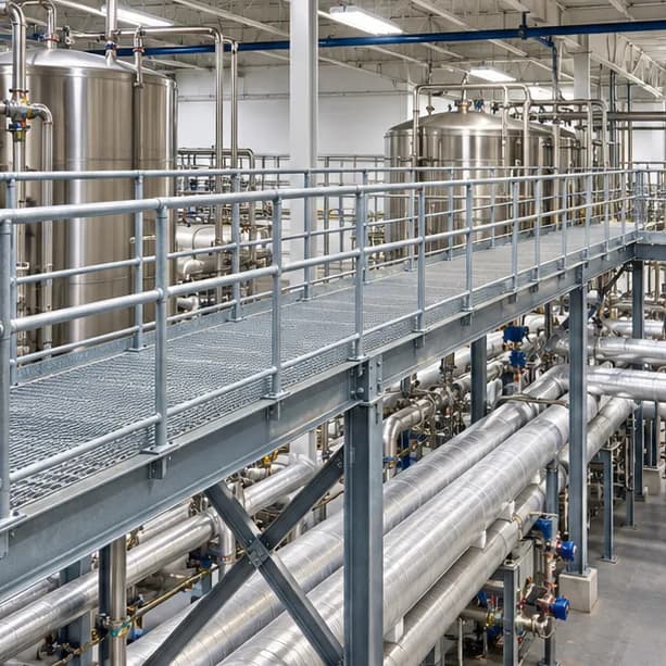
Process Facility Maintenance Walkways
Walkways and operator-access areas serving pumps, valves, filters and instruments. Drawings should identify equipment-side interfaces, safe-access geometry defined in project documents and modular panel arrangements where specified.

Elevated Catwalks and Crossovers
Longer spans or crossings over equipment and utility routes. Documentation may include framing arrangements, intermediate supports, grating layouts, handrail interfaces and references to the responsible designer's structural requirements.
Conceptual illustrative photography assets. Not completed customer projects.
Deliverables Matrix
What's Included in a Steel Platform Shop Drawing Package?
The final deliverable set depends on who is supplying the steel, how the platform is supported, whether a grating manufacturer provides panel drawings and which design information has been approved. A scope review confirms what is included before work starts.
| Deliverable | Typical Information | Why It Matters |
|---|---|---|
| General arrangement plans | Platform footprint, reference levels, access direction, adjacent equipment and site reference points | Aligns the access structure with the project |
| Platform framing plans | Beam and secondary member layout, orientation, piece references and framing interfaces | Organizes fabricated support members |
| Elevations and sections | Height relationships, platform levels, rail and equipment interfaces, support positions | Clarifies vertical fit and clearances |
| Assembly and part drawings | Member marks, cuts, plates, relevant holes and approved weld/bolt references | Supports fabrication and identification |
| Grating panel drawings | Panel breaks, bearing direction, openings, edge trim, supports and attachment references | Coordinates flooring fabrication and installation |
| Support and connection details | Approved beams, brackets, plates, base connections, anchors and interface conditions | Reduces unclear attachments |
| Access and edge protection | Specified guardrails, toe boards, stairs, gates and ladder interfaces | Coordinates the access package |
| Material and bolt schedules | Part identifiers, quantities and relevant grades when included in scope | Supports shop organization |
| Issue and revision records | Drawing revision identifiers and incorporated authorized changes | Helps prevent use of outdated sheets |
Flooring & Panel Coordination
Grating Layout Drawings: Panels, Bearing Direction & Openings
Grating is often one of the most coordination-sensitive parts of a platform package. A grating plan is not simply a hatch pattern over the platform footprint. Each panel needs a defined relationship to the supporting steel and the selected grating product.
The bearing bars are intended to transfer load to supports in the correct direction. Panel sizes, removable sections, clear openings, perimeter trim, access hatches and clip locations must match the manufacturer's product data and the approved support framing. A drawing that rotates a panel without reviewing bar orientation or support conditions risks creating a fit-up or performance issue.
For platforms around tanks, valves or motor assemblies, openings also need a coordinated purpose. A cutout may provide access to an operating component, allow an existing pipe to pass through a deck, or permit equipment removal. Its dimensions and edge framing need confirmation against the approved design and actual equipment envelope.
Grating selection may involve welded or press-locked products, serrated surfaces, heavy-duty bars, galvanized finishes and non-steel alternatives. The selection, required load/span performance and fixing method belong to the project specification and approved product submittal. Drawings should reflect the confirmed choice rather than invent it.
Essential Grating Coordination Items:
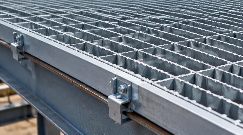
Galvanized Bar Grating Edge & Trim
Coordinated bearing direction, edge banding and structural support seats.
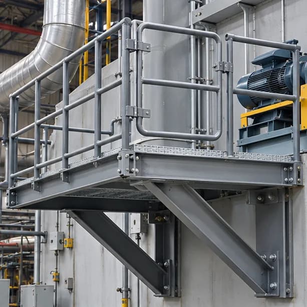
Cantilevered & Wall-Mounted Assemblies
Bracket geometry detailed strictly to approved engineer loading criteria.
Structural Framing & Supports
Platform Framing, Columns & Cantilever Support Conditions
A platform may stand on its own columns, attach to an existing steel frame, bear on a concrete support, or cantilever from a designed wall or equipment support frame. Each support condition creates different detailing requirements. The shop package should clearly identify the arrangement supplied by the responsible structural design professional.
For freestanding assemblies, framing plans and elevations coordinate primary beams, secondary members, bracing, base connections and the direction in which members are installed. For attached platforms, interface drawings should identify the existing steel or substrate, approved attachment points and any field dimensions still outstanding.
Cantilevered maintenance platforms deserve special attention because their connection arrangement is a critical part of the structural behavior. A detailer should not determine member sizes, anchor capacity, weld design or load paths independently. Missing design information belongs in an RFI so the engineer or approved delegated designer can provide direction.
When access platforms attach near doors, ductwork, machinery guards or inspection hatches, the drawings should also reserve the designated equipment space and avoid conflicts with maintenance operations.
Connection Engineering Coordination
Connection & Anchorage Details for Platform Steelwork
Clear connection references are essential when several trades interact around the same support structure. Platform framing might connect to building columns, support beams, embedded plates, or project-specific brackets. Drawings should show the intended location and orientation of these approved connections and keep the member references consistent across assembly views.
For bolted assemblies, drawing information may include the approved plate geometry, bolt quantities and types, hole configurations and field-versus-shop connection designation. Welded connections must reference the approved weld requirements and applicable fabrication documents. Anchor arrangements require particular care around concrete edges, substrate conditions, existing reinforcement and site measurement.
Any ambiguous support, undocumented embed or missing engineered connection should be raised for review before release. A detailing sheet is not a substitute for structural calculations or professional design approval.
| Interface | Information to Confirm |
|---|---|
| Beam-to-column | Approved connection arrangement, marks and orientation |
| Base plate to concrete | Approved anchor type, layout, substrate and edge conditions |
| Platform-to-existing steel | Verified supporting member and approved attachment method |
| Cantilever bracket | Responsible designer's connection and loading information |
| Grating to support | Product-specific fixing or clip arrangement |
| Guardrail post | Approved rail package and support connection |
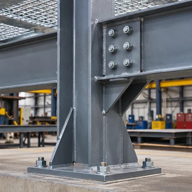
Column Base & Anchor Interfaces
Detailing hole patterns, anchor sizes, edge distances and grout thickness.
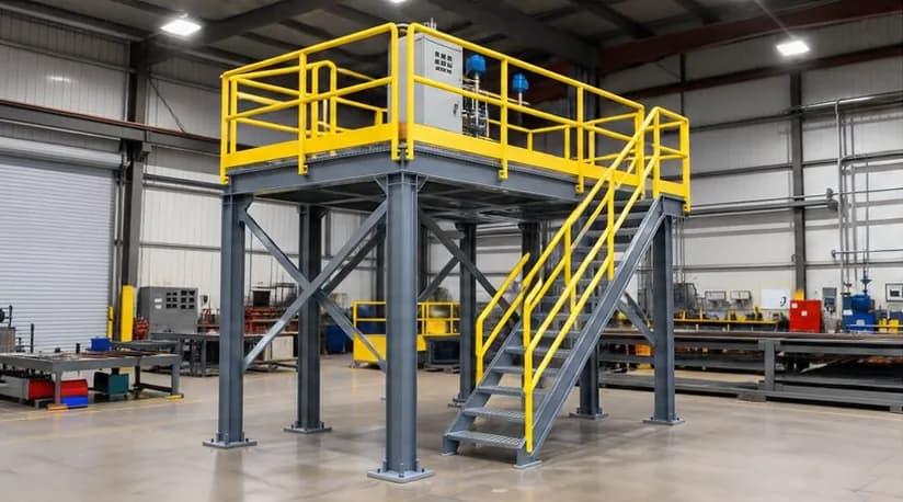
Access Route & Fall Protection Coordination
Connecting platform headers with stair stringers and perimeter guardrails.
Access Route Integration
Integrating Stairs, Guardrails & Access Openings
A usable platform requires a coordinated route into and out of the work area. Depending on the design, this may involve an industrial stair, ladder, alternating-tread device, access gate, removable rail section or other approved access assembly. The allowed access method varies by intended use, site conditions and applicable rules.
The platform drawing should locate stair or ladder arrival points, landing interfaces, framed openings and the guardrail breaks needed for entry. Where railing and stairs are detailed under separate packages, references must identify which trade supplies the components and who coordinates the connection positions. If your project includes independent stair flights or balustrades, review our dedicated Steel Stair Shop Drawings and Guardrail & Handrail Drawings services for component-specific scopes.
Toe boards, midrails and gates may be specified as part of fall and falling-object protection, but their applicability and details should come from the design and governing standard. Industrial workplace requirements under OSHA 1910.28 and 1910.29 should not be presented as universally governing every building or project.
For example, the edge at a removable grating opening might require a different access arrangement than the normal platform perimeter. That decision requires project-specific review, not a generic copied guardrail detail.
Retrofit & Brownfield Operations
Existing-Plant Coordination: Field Dimensions, Clearances & Revisions
Industrial access steelwork is often added after the surrounding process equipment has already been installed. Contract drawings may show a nominal pipe route or equipment envelope that differs from actual field conditions. A fabrication package should identify which dimensions are design-based and which require site verification.
The review should consider moving or removable equipment parts, valve operations, maintenance tools, safe access routes defined by the design, and temporary access needed during installation. Layout and grating openings must be coordinated with the current piping, electrical, mechanical and structural information provided by the project team.
Where a conflict is identified, the appropriate response is to document it and request direction through the project's RFI or design clarification process. Field measurement and scan information can assist coordination if supplied, but remote detailing does not imply the company personally conducts on-site surveys for every project.
Typical Field Coordination Conflicts Identified During Detailing:
Deliverable Previews
Steel Platform & Catwalk Shop Drawing Examples
Explore six illustrative sheets showing the types of information that may appear in a platform or catwalk detailing package. These conceptual diagrams demonstrate drawing organization and common component interfaces.
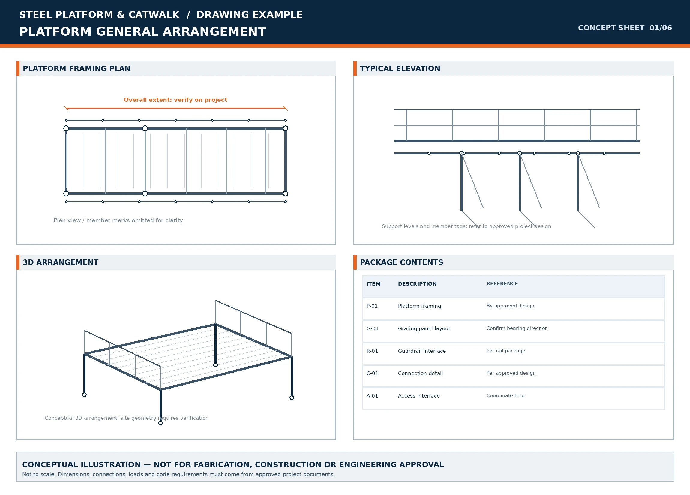
GENERAL ARRANGEMENT & 3D OVERVIEW
Scale: 1/4" = 1'-0"Platform General Arrangement
Conceptual platform footprint, elevation, 3D arrangement and drawing package references.
CATWALK FRAMING & MEMBER PLAN
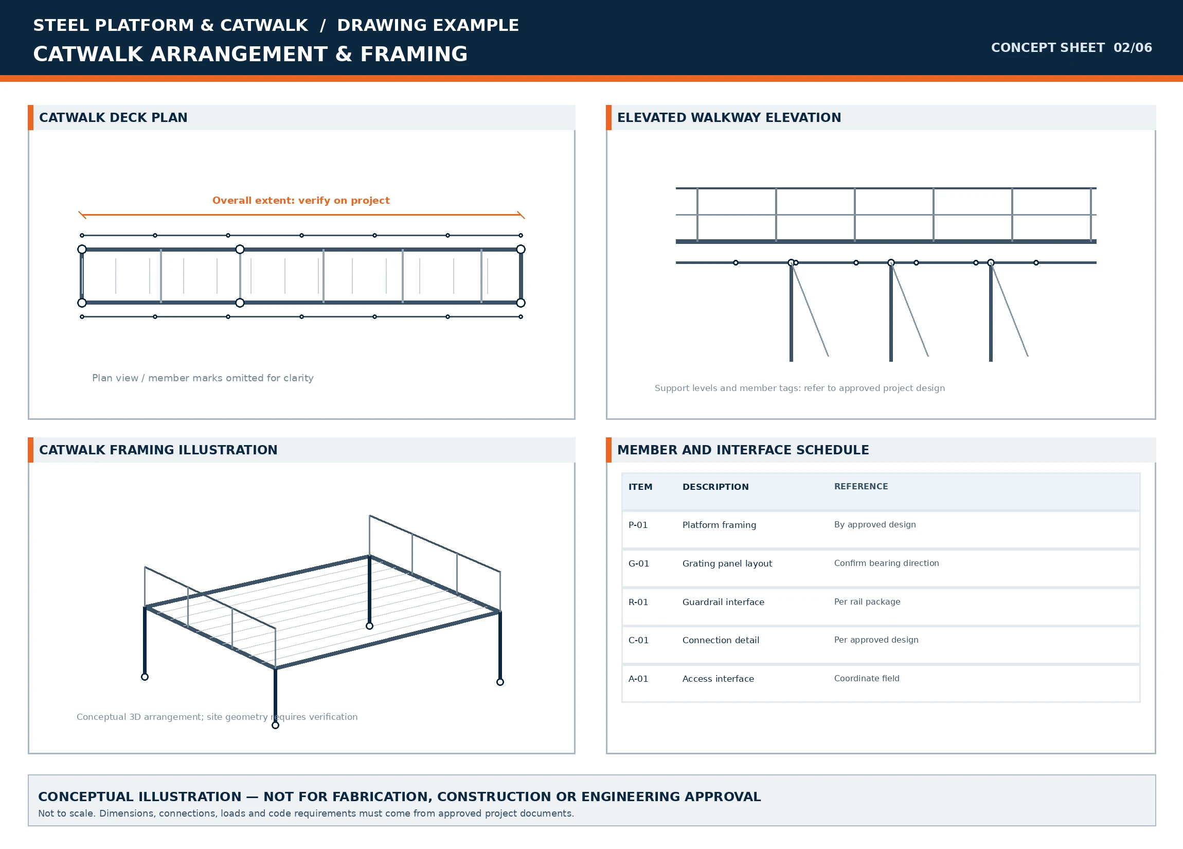
Scale: 1/2" = 1'-0"Catwalk Framing Layout
Illustrative catwalk support framing, continuous walkway arrangement and member reference organization.
BAR GRATING DECK & OPENING SHEET
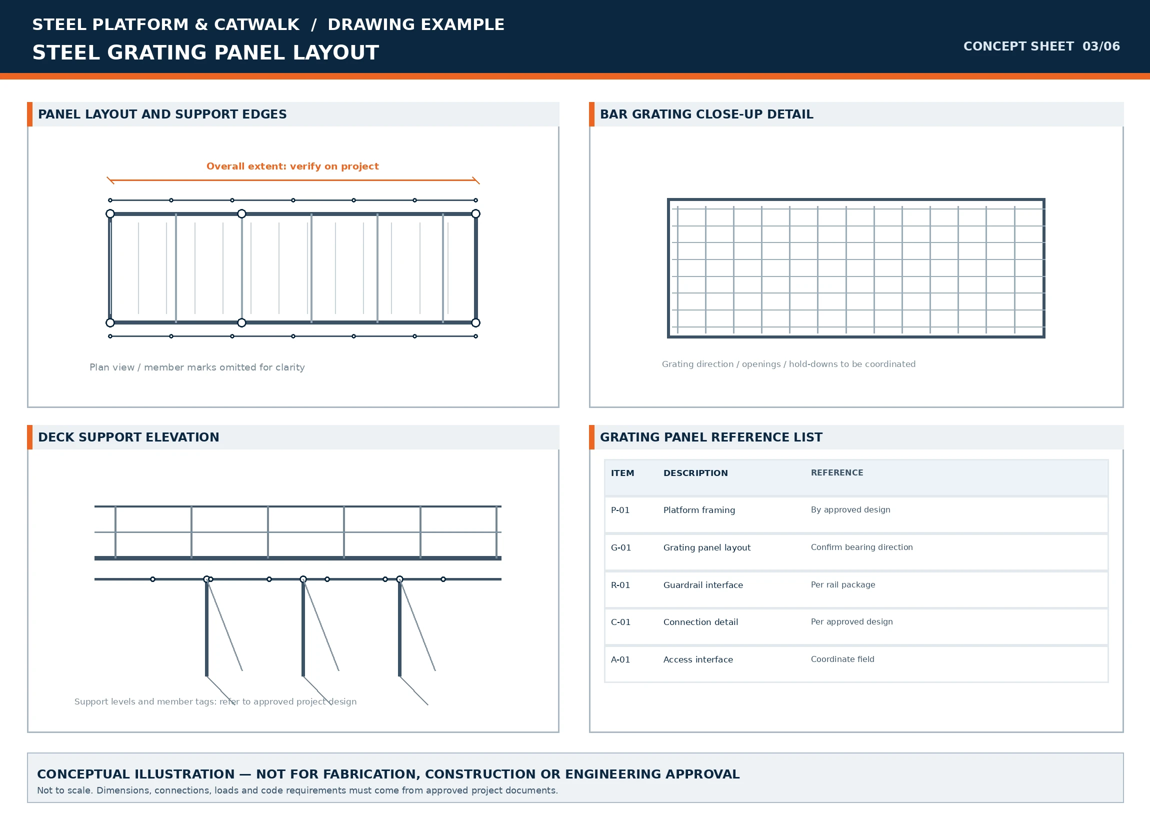
Scale: 1/2" = 1'-0"Steel Grating Panel Layout
Panel layout concept, bar grating detail and product-related support information.
SUPPORT & ANCHORAGE DETAIL SHEET
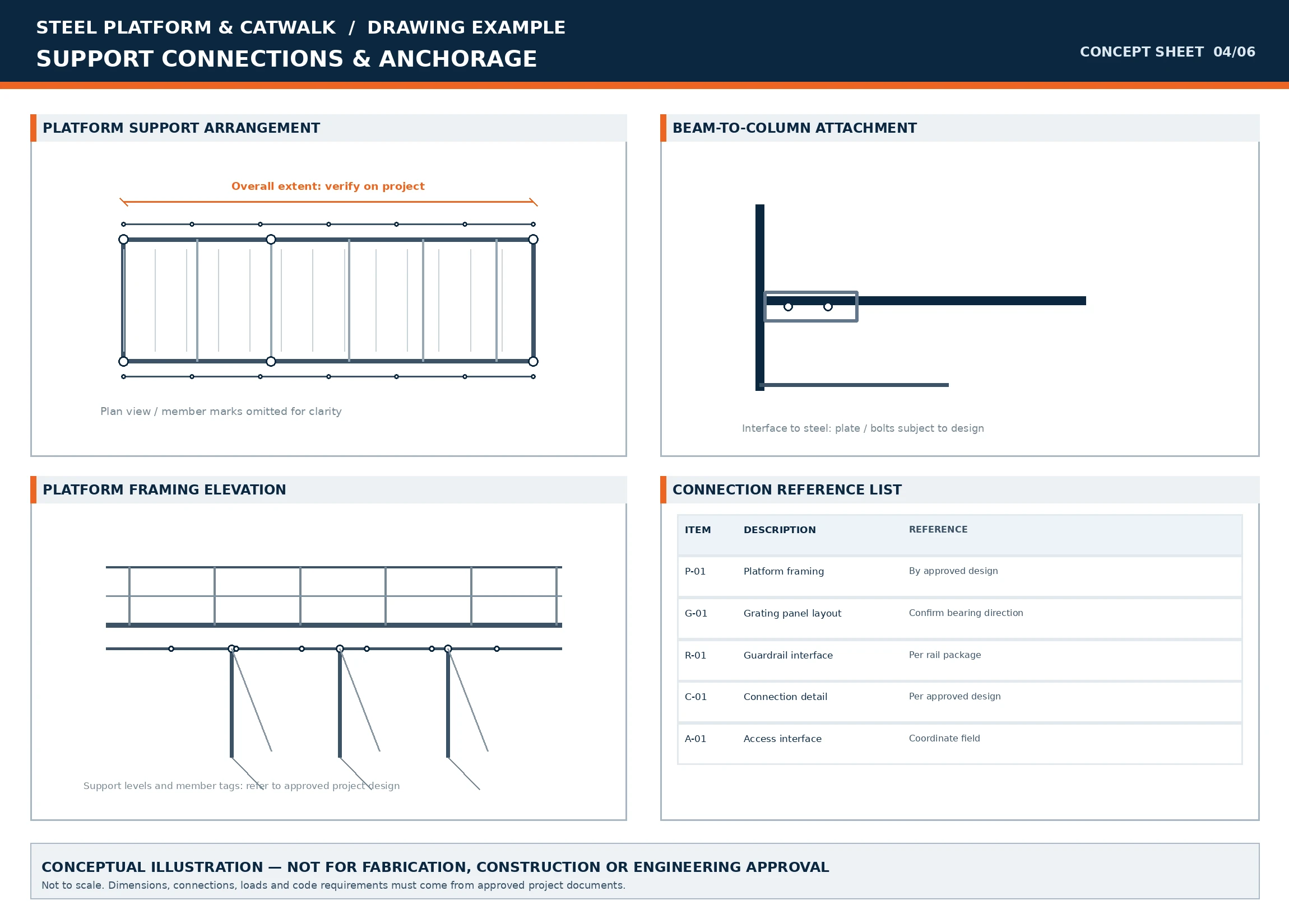
Scale: 1" = 1'-0"Platform Support Connections
Simplified steel support and attachment references for coordination discussion.
ELEVATED CROSSOVER & STAIR ASSEMBLY
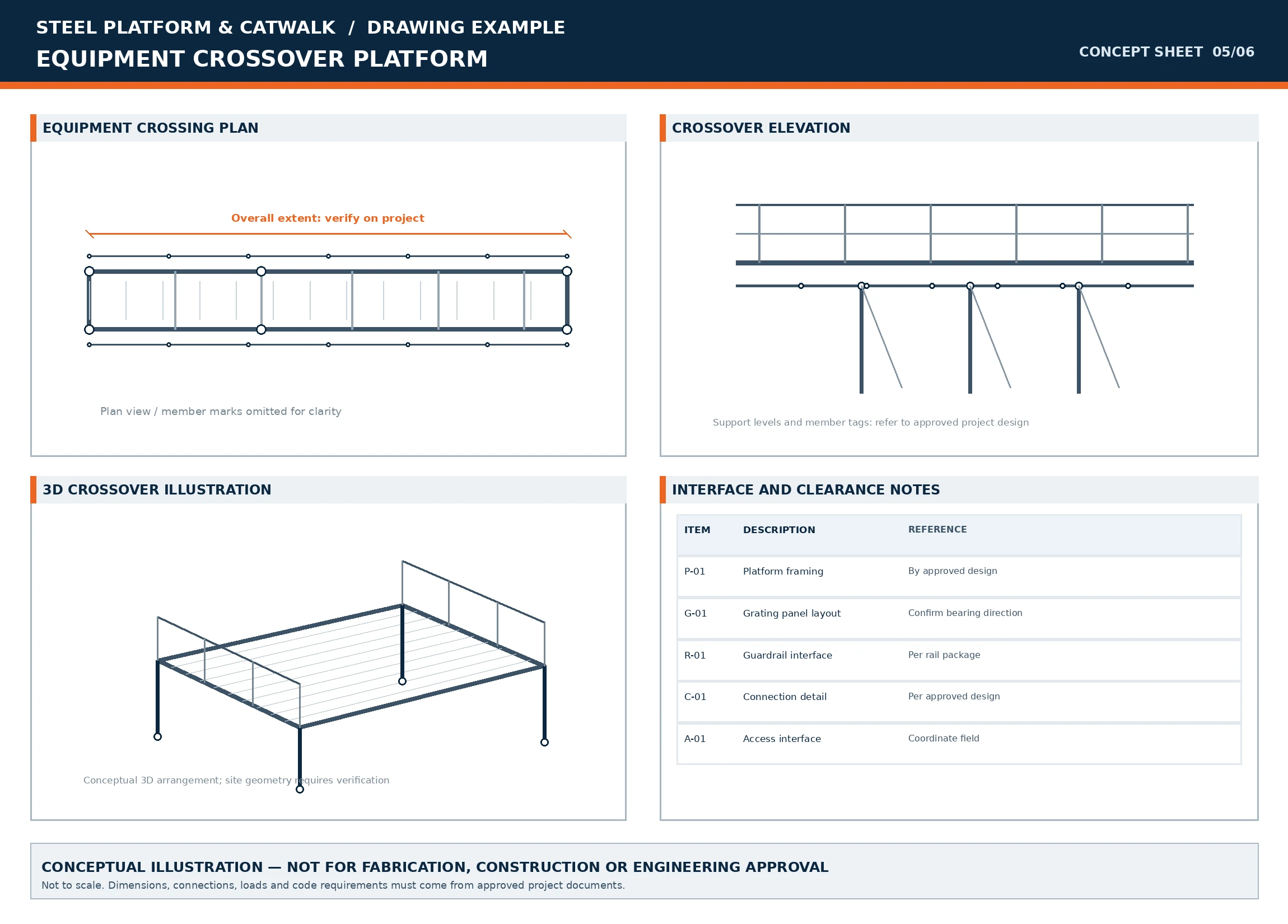
Scale: 1/2" = 1'-0"Equipment Crossover Details
Conceptual elevated crossover arrangement with framing, guardrail and surrounding-equipment interfaces.
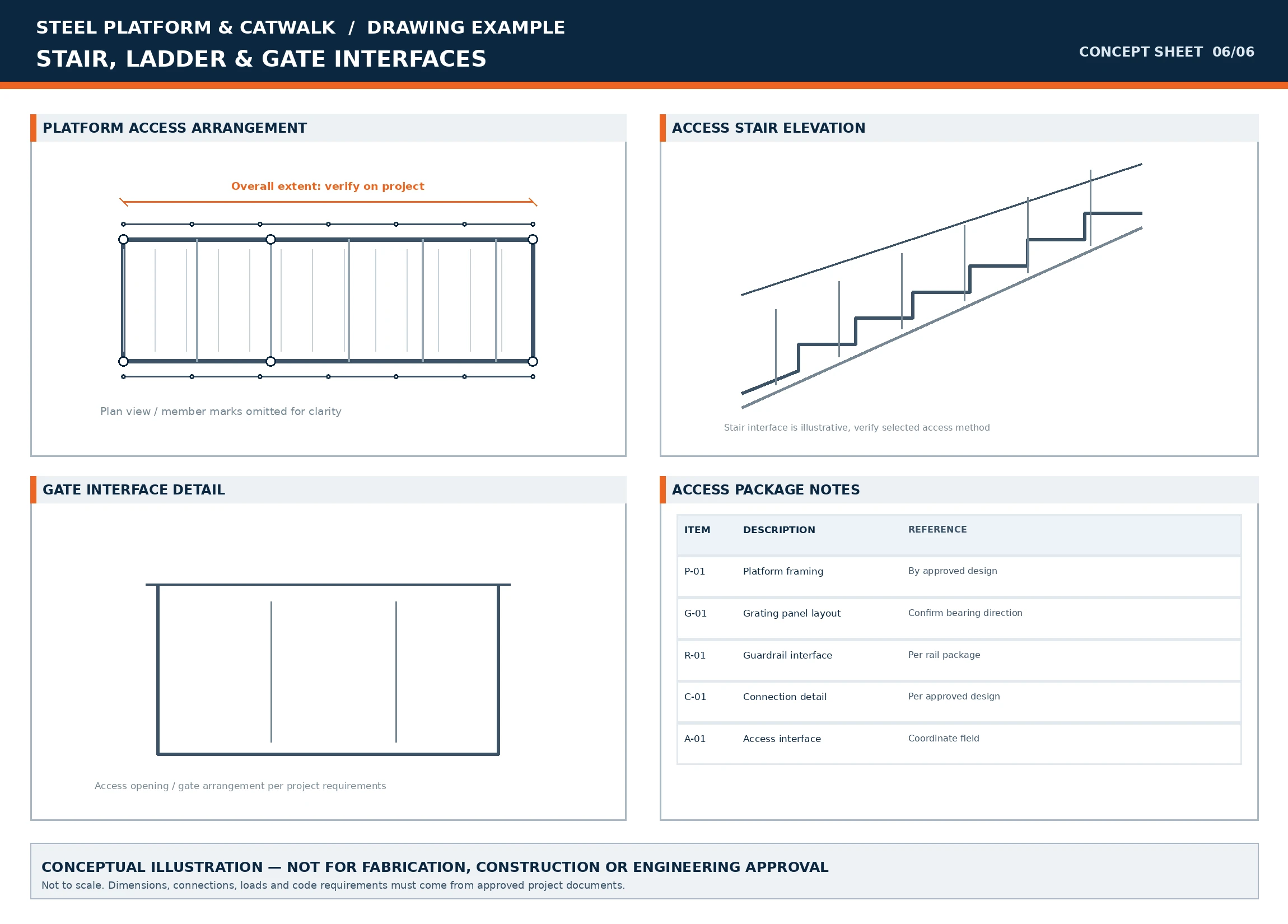
ACCESS INTEGRATION & SAFETY GATE DETAIL
Scale: 3/4" = 1'-0"Access Stair & Gate Interface
Illustrative access opening, stair interface and component coordination sheet.
Quotation Preparation
What to Send for a Steel Platform Drawing Quote
A useful quotation begins with a clearly marked platform and catwalk scope. Send available architectural and structural drawings, equipment layouts, current plant arrangements and details defining the steel members or supports. Include specifications for grating, guardrail systems, materials and finishes where those have already been selected.
A single overview drawing often does not explain existing conditions. If a platform wraps around equipment, share site photos, measured clearances or existing CAD/3D data where available. Identify drawing changes, required submittal formats and the review deadline so the drafting package can be scoped accurately.
Structured Drafting Procedure
How Platform & Catwalk Shop Drawings Are Prepared
Our structured procedure keeps fabricators and site teams aligned from initial plan review through final submittal issue.
Review the Work Package
We review the assigned platform scope, source documents, support conditions, grading or grating product data, access details and the requested drawing deliverables.
Identify Clarifications
Missing design information, uncertain field dimensions, support conflicts and interface questions are documented for confirmation by the responsible project parties.
Prepare the Drawing Set
Layouts, assembly views, framing details, grating references and the agreed schedules are organized using the confirmed project documents and required drawing standards.
Check for Consistency
Drawing references, component marks, material schedules and linked views are checked for consistency with current source information and authorized changes.
Issue and Revise
The agreed deliverables are submitted in the required formats. Authorized review comments and contract revisions are incorporated within the defined revision scope.
Standard drafting does not imply automatic engineer approval or instant fabrication release. All submittals follow the formal contract review procedures established for your project.
Deliverable Specifications
Platform Drawing Deliverables & File Formats
PDF drawing sets are suitable for review, markups and controlled issue packages. Editable CAD files such as DWG or DXF may be supplied where requested and agreed. Some projects also require compatible 3D model exports, part schedules or machine-related files, depending on available project data and the selected detailing workflow.
The quotation should identify what files are included and which software/model standards apply. Do not imply that every package includes IFC, CNC/DSTV, fabrication nesting or a fully coordinated plant model.
Coating & Environmental Factors
Material Grades, Galvanizing & Industrial Exposure Conditions
Platform and catwalk steelwork may be exposed to outdoor weather, cleaning agents, temperature variation, industrial process conditions or frequent maintenance activity. Fabrication documents should reproduce the specified material and coating requirements without substituting a generic finish.
A galvanized steel platform has different fabrication and detailing considerations from a painted indoor access platform or a stainless steel assembly. Hole arrangements, grating attachment methods, field connections and any finish-sensitive surfaces should be coordinated with the selected system and the project's written specifications.
Where removable components or inspection access is required, drawing notes should identify the relevant parts without implying an unapproved field modification. Material selection, corrosion classification and structural suitability remain decisions for the responsible project design and procurement teams.
Proactive Quality Assurance
Common Platform & Catwalk Detailing Issues to Resolve Early
These are not minor drawing aesthetics. They affect ordering, fabrication, coordination and installation. A useful detailing package makes unresolved information visible before it is treated as fabrication instruction.
| Issue | Likely Consequence | Recommended Drawing-Stage Action |
|---|---|---|
| Grating bearing direction conflicts with support spacing | Panel may not bear as specified | Confirm product and support design |
| Pipe penetration omitted from deck plan | Field cutting or rework | Verify opening size and location |
| Platform level differs from equipment access level | Misaligned access | Reconcile elevations and site data |
| Undocumented anchor/base connection | Unresolved fabrication interface | Request approved connection design |
| Guardrail gate conflicts with machinery | Access restrictions | Coordinate opening and operating envelope |
| Stair landing reference is outdated | Geometry changes | Incorporate current approved revision |
| Unclear division between grating supplier and steel fabricator | Duplicate or missing deliverables | Define trade scope in submittal register |
| Inaccurate field dimensions at existing building | Installation and fit-up conflict | Identify survey/field verification requirement |
Regulatory & Engineering Boundaries
Applicable Standards & Professional Responsibility Boundaries
Industrial walking-working surfaces must be reviewed against the requirements that apply to their particular workplace, operation and project. OSHA 29 CFR 1910.28 addresses specified fall-protection duties for general-industry walking-working surfaces. OSHA 1910.29 provides detailed criteria for guardrail systems and certain falling-object protections. OSHA 1910.25 addresses covered industrial stairways. These provisions do not replace other rules that may apply to construction activities, building occupancies or special-use facilities.
Steel grating product selections and detail arrangements should be informed by the specified grating manufacturer's information and relevant NAAMM guidance. The bearing-bar direction, span, fastening and load performance must be established through the approved design and product data, not inferred from a conceptual website drawing.
The AISC Code of Standard Practice establishes structural-steel contracting conventions within its applicable scope. It does not mean that every grating, ladder or catwalk item is automatically included in the primary structural-steel scope. Project-specific trade boundaries and design responsibilities should be established in the contract documents.
Some equipment platforms and mezzanines have distinct treatment under the applicable building code. Their classification is a design and permitting matter, not a label to assign based only on appearance.
The service described on this page provides drafting and detailing support for the confirmed scope. Structural member design, load calculations, stamped drawings, temporary works, lifting plans, OSHA workplace determinations, inspection and final approvals require separately designated qualified parties. Do not claim the company's drawings are inherently OSHA-compliant or PE-approved.
Target Stakeholders & Sectors
Steel Platform Detailing for Fabricators & Industrial Contractors
Steel fabricators need assembly and individual-part information organized for production. Industrial contractors need drawing references that coordinate access steel with existing piping and equipment. Plant owners and maintenance teams need clearly documented locations, openings and service access requirements from the design team. General contractors use the submittal set to coordinate steelwork with mechanical, civil, electrical and other trades.
The service is relevant to manufacturing plants, water and wastewater facilities, distribution centers, processing sites, rooftop mechanical areas and industrial renovation projects. Examples of these facility types are typical applications, not claims of named past customers or completed work.
Steel Fabricators
Shop assembly drawings, member marks, hole spacing, and cutting lists organized for shop cutting and fit-up.
Industrial Contractors
Field coordination references for pipe racks, pump stations, tanks, and mechanical machinery access decks.
Plant Maintenance Teams
Verified maintenance clear spaces, removable hatch locations, and safe valve operating access routes.
General Contractors
Submittal sets coordinated across trades, preventing clashes between structural steel, piping, and electrical conduits.
Cost & Turnaround Factors
Steel Platform & Catwalk Drawing Cost Factors
Platform drawing effort depends on the number of unique assemblies, overall layout, support complexity, grating schedules, equipment interfaces, source drawing quality, required modeling and review cycles. A repeated walkway with clear approved details is a different drafting assignment from a retrofit platform around existing equipment with many unresolved openings and support conditions.
The clearest route to a useful quotation is to submit the latest contract drawings, a marked platform/catwalk list, known field conditions, material and grating specifications, required file formats and target issue dates. The response should define included sheets, exclusions and revision expectations. Do not publish invented price-per-sheet figures or universal turnaround claims.
For broader project budgeting, contractors can also review construction estimating and quantity takeoff services when planning steel scopes and related materials.
Common Questions
Steel Platform & Catwalk Drawings FAQs
Clear answers regarding drafting scope, grating layouts, file deliverables, and engineering boundaries.
Need Steel Platform or Catwalk Shop Drawings?
Share your platform layouts, equipment interfaces, steel support details and required submittal dates. We will review the scope and prepare a quotation for the drawings and deliverables your project needs.