
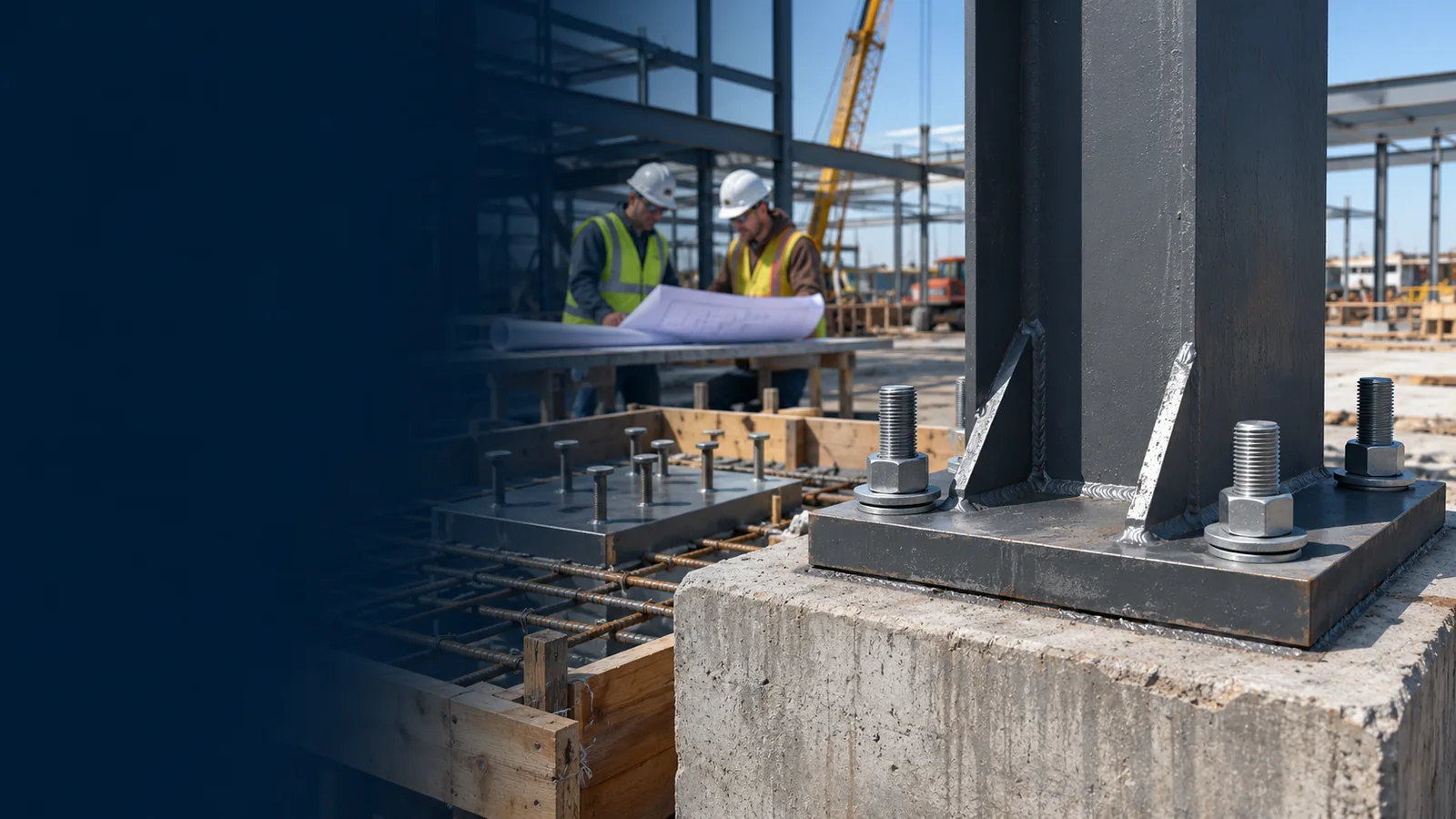
Anchor Bolt & Embed Plate Drawings for Fabricators & Contractors
Anchor rods and embedded steel plates connect structural steel work to concrete foundations, walls, and supporting elements. Our drawing services organize anchor rod setting plans, column base plate details, embed plate assemblies, and coordination information for the project’s approved scope. Send your drawings and specifications so we can review the required deliverables and prepare a quotation.
Definition & Detailing Scope
Drawings That Coordinate Structural Steel with Concrete
An anchor rod setting plan identifies the intended location and orientation of anchor rod groups that secure structural steel components to a concrete element. The drawings typically use structural grids, centerlines, reference elevations, setting marks, and related base plate geometry. They provide the coordination information the project team needs before items are fixed in place or concrete is poured.
An embed plate shop drawing documents a steel plate or assembly intended to be cast into, or otherwise connected to, concrete. Depending on the approved design, the assembly may have headed studs, anchors, reinforcing interface details, welded fittings, or other components. The drawing identifies the fabricated item and references its placement in the structure.
The word anchor bolt is common in construction searches. For structural steel column anchorage, AISC frequently uses the term anchor rod to distinguish foundation anchorage from structural bolting between steel members. The right terminology on a project should follow the contract and approved details.
An effective drawing set connects three sets of information: the engineering design and material specifications, the steel fabricator's component geometry, and the concrete contractor's setting-out requirements. Inconsistencies should be identified for clarification rather than silently resolved by the detailer.
Drawings are coordinated from project-approved documents. Unresolved foundation levels or anchor discrepancies are flagged for clarification prior to concrete placement.
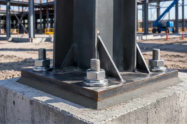
Column Base & Anchor Interface
Coordinating anchor rod projections, leveling nuts, and grout clearance.
Assemblies & Component Scopes
Typical Anchor Rod and Embedded Steel Drawing Scopes
A single project may use several types of anchorages and embeds. Each requires a different combination of layout, fabrication, and placement details.
Column Base Plates
Base plate dimensions and orientations, approved hole patterns, plate marks, steel-column interfaces, washer arrangements, and references to grout or bearing levels. Anchor design and final plate sizing are engineering responsibilities.
Anchor Rod Groups
Setting locations, grids, centerline dimensions, group orientation, rod marks, approved material references, top-of-rod or projection information, and related schedule entries.
Anchor Rod Templates and Cages
Setting templates or assemblies used to keep multiple rods in their specified arrangement before and during concrete placement. Show hole patterns and assembly relationships based on the authorized project design.
Headed-Stud Embed Plates
Plates fitted with approved headed studs or other anchorage components, including plate geometry, connection references, stud arrangement, identification and required fabrication notes.
Wall and Slab Embed Plates
Location drawings for plates at walls, slabs, edges or other interfaces that will receive steel framing, brackets or supports. Coordinate plate face, elevation and the receiving assembly.
Equipment and Specialty Anchors
Document approved anchor locations and mounting interfaces for project-specific equipment or fabricated supports where assigned. Do not imply responsibility for machine anchorage design.
Precast Embed Interfaces
Cast-in plate locations and orientation references coordinated with precast elements, related tolerances from the project documents, and connection requirements.
Bearing or Support Plates
Approved bearing plate and attachment geometry shown alongside the relevant steel member and concrete support condition when included in the package.
Looking for cast-in precast element coordination? Review our precast and tilt-up embed references.
Deliverables Package
From Foundation Layouts to Fabrication Schedules
The exact package depends on the contract and which party is responsible for furnishing, placing, and reviewing the material. Typical drawing deliverables include:
| Deliverable | Information Documented | Coordination Purpose |
|---|---|---|
| Anchor rod setting plan | Building grids, rod-group locations, centerlines, marks and orientation | Helps align foundation setting with steel layout |
| Base plate and column details | Plate outline, approved holes, column reference, elevation and interface | Relates fabricated plates to specified column positions |
| Embed plate location plan | Plate marks, locations, elevations, face orientation and receiving steel | Supports concrete-form and steel trade coordination |
| Embed plate fabrication sheet | Plate geometry, studs or other approved attachments, weld references, marks | Organizes fabrication of the embedded item |
| Setting-template detail | Grouped-rod geometry, template orientation and identification | Supports required setting arrangement |
| Anchor rod and embed schedule | Item marks, approved descriptions, quantities, locations, revisions | Keeps repeated items traceable |
| Section and interface views | Concrete face, approved embed relationship, steel support geometry | Communicates the interface between trades |
| Revision and RFI records | Drawing issues, approved updates and unresolved questions | Reduces conflicting site instructions |
Pre-Pour Layout Coordination
Locating Anchor Rod Groups Before the Concrete Pour
Anchor rod setting plans are useful only when they identify the rod groups in the correct building coordinate system. A dimension from a slab edge cannot automatically replace a structural grid dimension. The drawing must follow the project's agreed reference lines, revisions and elevations.
A typical sheet organizes column locations, reference grids, rod-group marks, plate or template orientations, and the approved anchor arrangement. Where required, it identifies top-of-rod information, finished concrete elevation, reference elevation or an installation note supplied by the design documents.
Rotated column bases, nonstandard rod patterns and closely spaced adjacent anchors can create errors if the orientation is not unambiguous. Where a plate or foundation detail conflicts with a later architectural or structural revision, the discrepancy should be raised through the project's review process before field placement.
Practical Coordination Checklist:
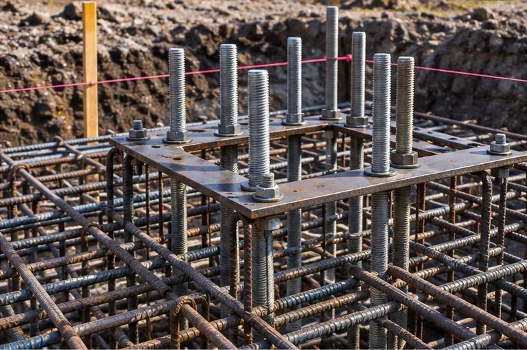
Setting Template & Formwork Alignment
Ensuring anchor rod clusters maintain exact coordinate spacing during concrete placement.
Column Base Interface Geometry
Plan, elevation, weld prep, and bearing level coordinates.
Structural Bearing Interfaces
Base Plate Geometry and Steel-to-Foundation Interfaces
The steel column base is an interface between the structural frame, bearing plate, anchor rods, grout or bearing system, and concrete support. A base plate drawing should communicate the approved plate profile, orientation, connection to the column and the relationship to the anchorage layout.
Project details may call for stiffeners, leveling arrangements, grout clearances, holes or other connection components. Drawings should document those approved requirements, not invent them. Column-base support conditions also vary across braced frames, gravity columns and moment frames, so one generic base detail should not be applied to every location.
Particular care is needed where a hole pattern appears symmetrical but the supporting column, stiffener or brace connection is not. A clear mark and orientation reference avoids a plate being turned incorrectly during fabrication or setting.
Headed Studs & Cast-In Plates
Embedded Steel Plates, Headed Studs and Attachment Interfaces
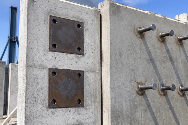
An embedded plate may be placed in a concrete wall, slab, pedestal or precast element to create an attachment point for later steel work. A fabrication sheet should show the selected plate size, orientation, approved anchoring components, weld references and identifying mark. The corresponding location drawing should show where the fabricated assembly belongs in the concrete work.
Stud location matters because closely grouped studs or plates can conflict with reinforcement, sleeves, openings and other embeds. Stud length, type, welding requirements, plate thickness and anchorage design are not drafting guesses. They must come from the engineer-approved project requirements and the applicable product or welding procedures.
For exposed or architecturally sensitive conditions, surface level, embed projection and the planned interface with adjacent finishes may require additional coordination. A plate shown at the wrong concrete face can cause more difficulty than an otherwise accurate fabrication drawing.
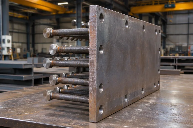
Headed-Stud Embed Plate Assembly
Plate layout, stud spacing, and identification mark.

Shop Stud Welding & Fabrication
Welding references coordinated to AWS and project requirements.
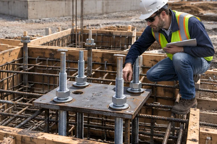
Anchor Rod Cage & Rebar Inspection
Coordinating anchor cluster geometry with dense reinforcing steel.
Interference Management
Coordinating Setting Templates with Formwork and Rebar
A template or rod cage is intended to keep an approved group of anchors in a controlled relationship during placement. The drawing should make the template orientation, rod arrangement and relevant assembly marks clear. The actual installation method, bracing and construction means remain the responsibility of the project parties assigned to perform the work.
Embedded items can interfere with top reinforcement, ties, stirrups, wall bars or congested foundation areas. The package should flag these interfaces early. A detailer must not relocate reinforcing steel, change anchor embedment, bend rods or shorten studs without approval from the responsible designer.
Where a conflict is discovered, identify the affected rod group, grid/level, drawing references and a proposed clarification question. Keep the final geometry based on written authorization rather than an assumed field workaround.
Concrete-to-Steel Transitions
Detailing Steel Attachments to Concrete Walls and Slabs
Wall and slab embeds can support structural steel members, edge angles, equipment platforms, canopies or other assigned components. Their drawings need to link the embedded item to the intended receiving steel, the actual concrete face and the relevant project elevation.
The same plate may appear in structural drawings, a steel shop detail and an embedment plan. Every drawing should identify the same mark, orientation and revision. Differences between plan and elevation views, particularly at sloped slabs, stepped walls or offsets, should trigger a coordination review.
When a bolted or welded steel component connects to an embed, the connection design must be supplied by the responsible engineer or authorized delegated design party. The drawing service documents approved geometry and fabrication references; it does not independently establish connection capacity.
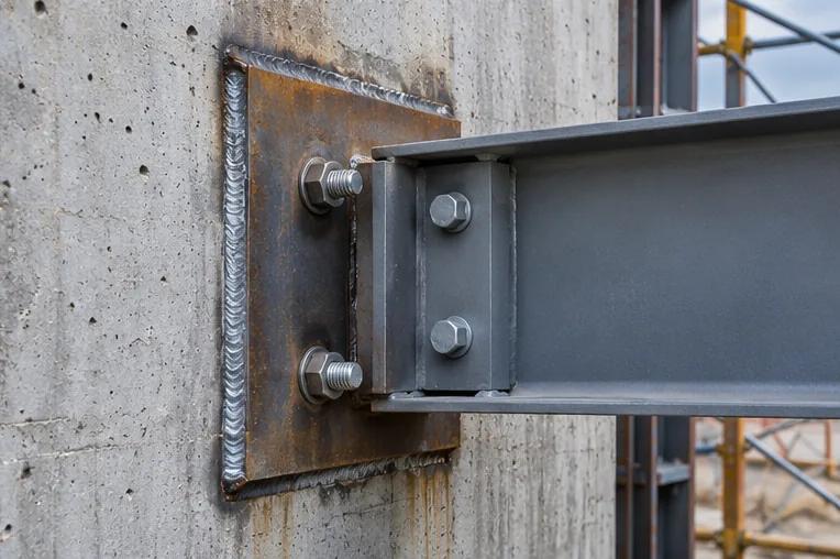
Wall Embed Connection Interface
Coordinating receiving steel bracket with cast-in wall plate face.
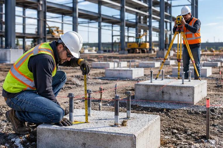
Field As-Built Survey Verification
Comparing installed anchor rod locations against approved setting drawings.
Quality Verification & Standards
What Happens Between Approved Drawings and Field Placement?
An approved embedment drawing is a reference for placement. Actual site work also involves setting-out, anchorage restraint during placement, concrete operations, surveying and verification. Those activities should not be confused with preparation of the drawing package.
AISC 303-22 §7.5 describes standard-practice responsibilities for setting anchor rods and other embedded items against approved embedment drawings. It also addresses as-built surveys and corrective action. Contract documents may assign responsibilities differently, and the project team must identify its applicable requirements.
For a drafting provider, a useful coordination role is to record the current approved setting plan, identify the intended anchor marks and respond to documented discrepancies. It is not appropriate to claim that a drawing itself confirms installed anchor tolerances or that the drafting team performed a field survey.
If a site survey finds misplaced anchors, do not instruct crews to torch, bend, weld, enlarge or relocate material without an authorized engineered repair or design resolution.
Deliverable Previews
Anchor Bolt & Embed Plate Drawing Examples
Explore six conceptual drawing examples showing the typical organization of anchor setting plans, base plate details, embedded steel plates and coordination schedules. These illustrations show drawing categories, not completed client jobs or approved fabrication documents.
Illustrative drawing samples only. Not approved for fabrication, field setting, construction, engineering design, or code compliance verification.
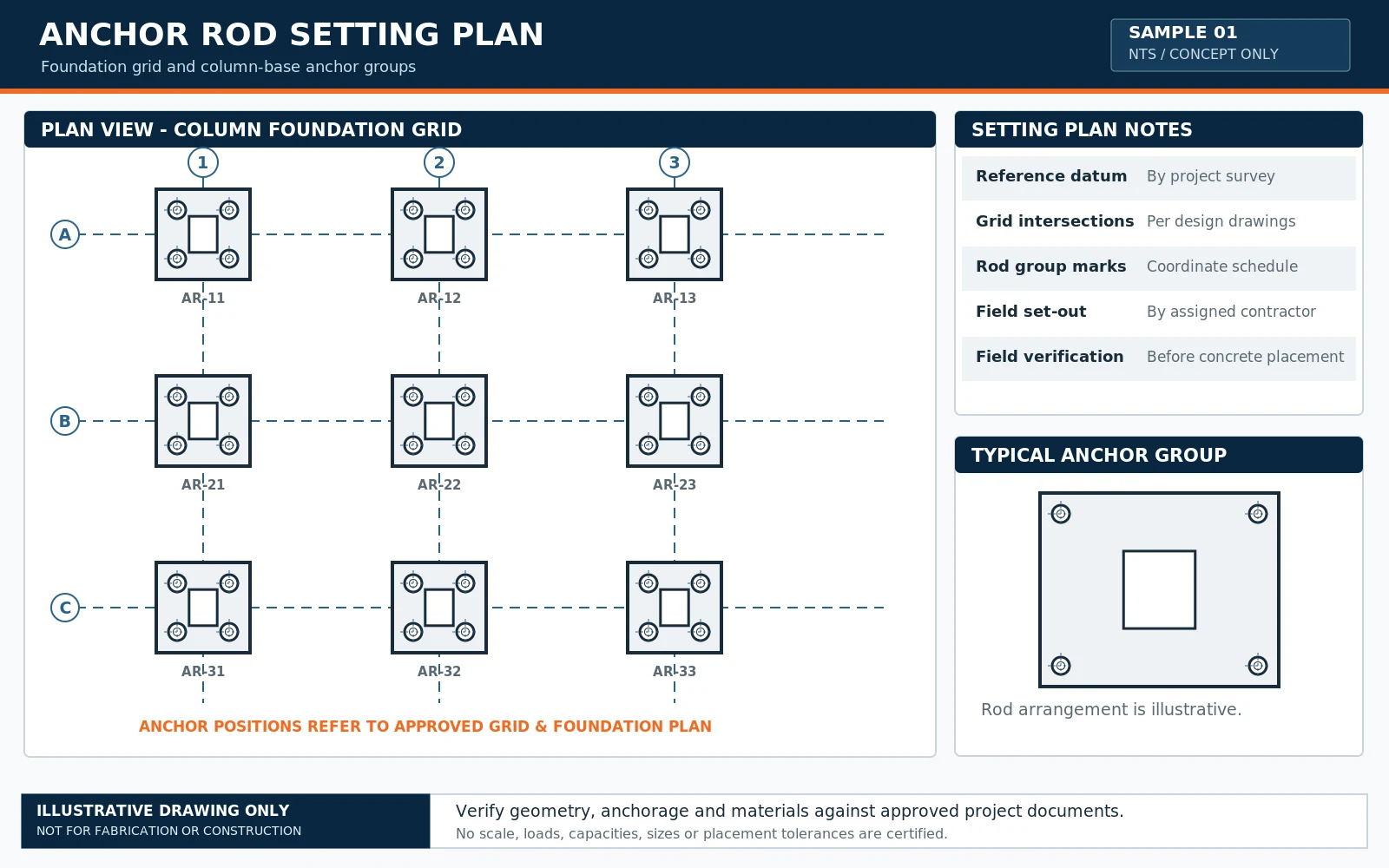
FOUNDATION GRID & SETTING-OUT PLAN
Scale: 1/8" = 1'-0"Anchor Rod Setting Plan
Building-grid references, column/rod group marks and conceptual setting-out arrangement.
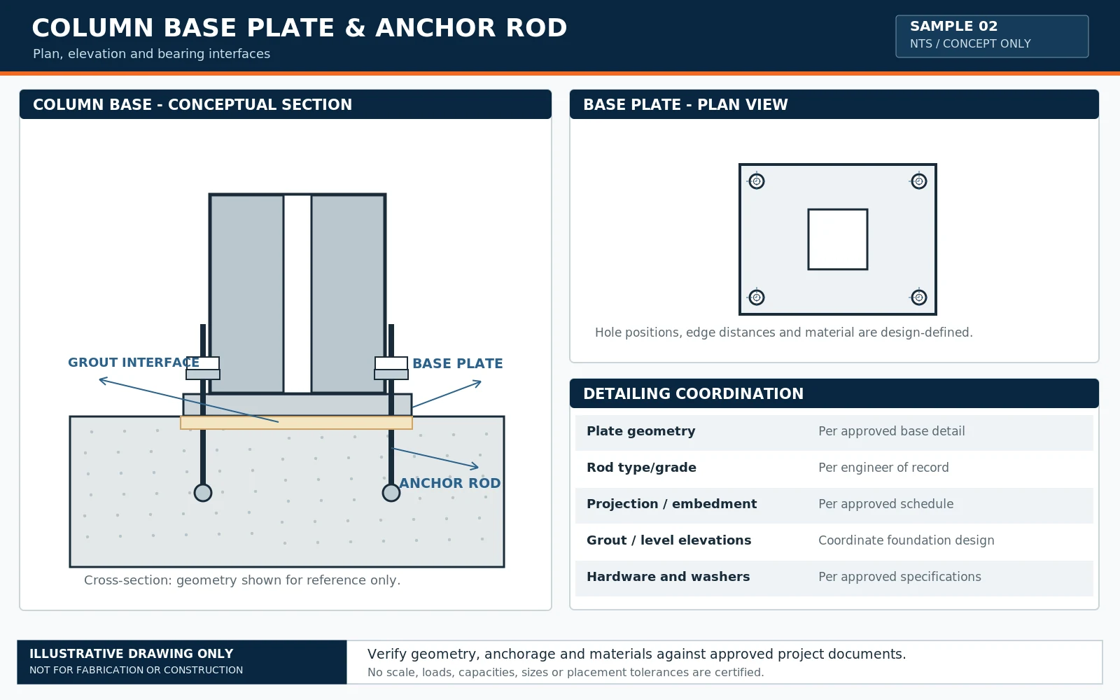
STEEL-TO-CONCRETE BEARING INTERFACE
Scale: 1" = 1'-0"Column Base Plate & Anchor Rod Detail
Conceptual base plate plan and section showing a steel column-to-concrete interface.
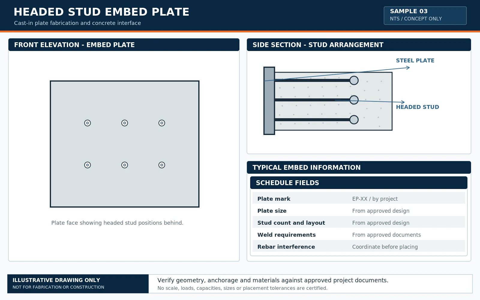
FABRICATION DETAIL FOR CAST-IN EMBED
Scale: 1-1/2" = 1'-0"Headed-Stud Embed Plate Detail
Plate views and stud-layout illustration for an embedded attachment assembly.
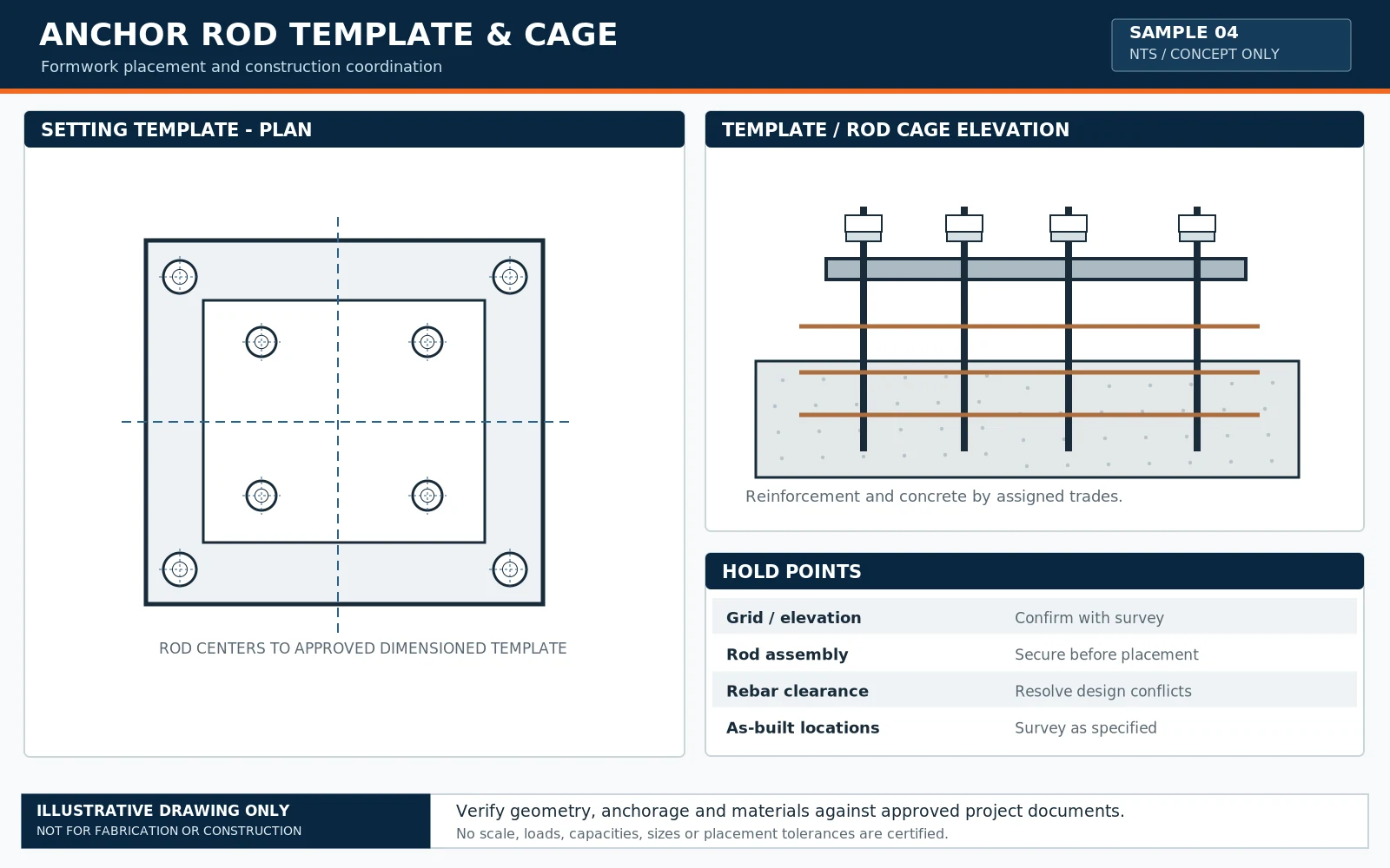
RIGID TEMPLATE & PRE-POUR ARRANGEMENT
Scale: 1" = 1'-0"Anchor Rod Template & Cage Detail
Conceptual rod-group assembly and template arrangement coordinated with concrete works.
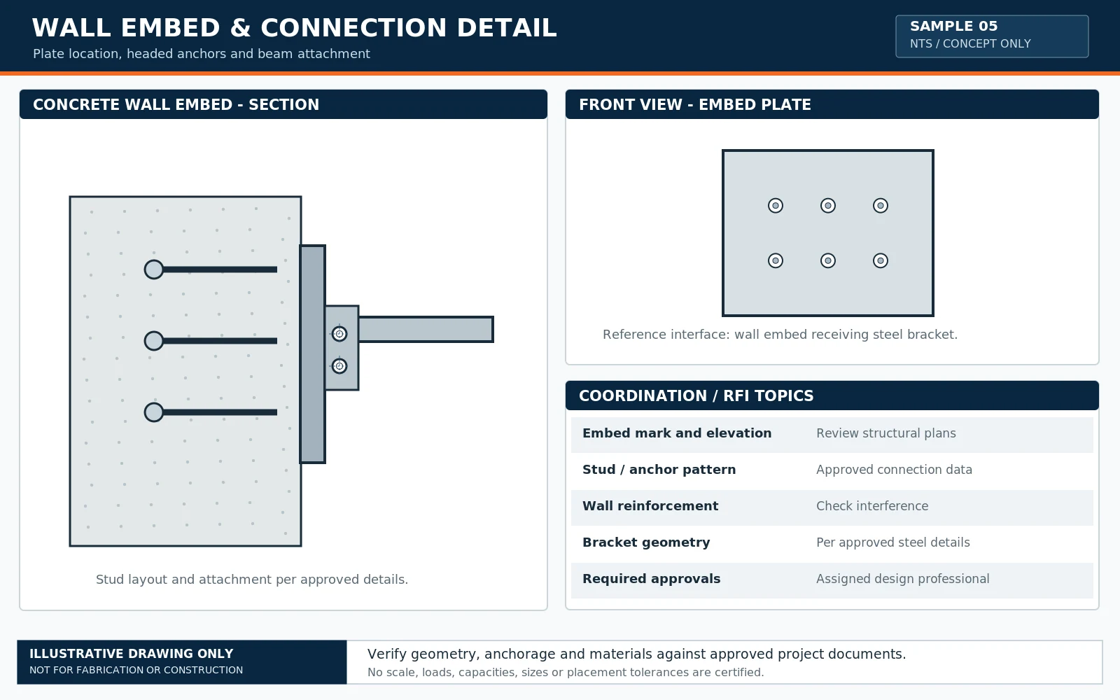
WALL INTERFACE & RECEIVING STEEL SUPPORT
Scale: 1" = 1'-0"Concrete Wall Embed Connection
Typical-looking wall embed and receiving steel interface, shown for educational illustration.
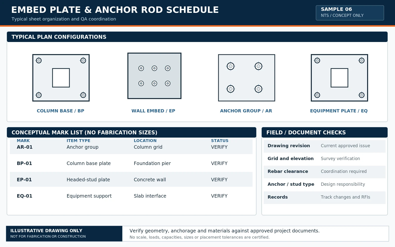
SCHEDULE REGISTER & QUALITY RECORDS
Scale: N.T.S.Embed Plate Schedule & QA Checklist
Example item marks, coordination fields and drawing review checklist structure.
Error Prevention & Review
Details Worth Checking Before a Foundation Pour
The purpose of these checks is to improve communication before work proceeds. Drawing review does not replace engineering design verification, installer responsibilities or physical inspection.
| Potential Issue | Why It Matters | Documentation Response |
|---|---|---|
Grid revisions do not match | Rod groups can be located using superseded references | Reconcile current structural/foundation drawings and revision dates |
Anchor group rotated incorrectly | Base plate may not fit the intended column direction | Identify orientation explicitly on setting plan |
Concrete elevation and rod projection differ | Inadequate or inconsistent intended interface | Request approved elevation and projection information |
Rebar clashes with embedded plates or rods | Assembly does not fit within reinforced concrete | Raise RFI to responsible design/placement parties |
Base plate pattern disagrees with foundation detail | Fabrication and site anchor locations conflict | Cross-check marks, plate drawings and approved details |
Wrong embed face or opening reference | Installed plate may face the wrong direction or level | Clarify face, elevation, orientation and receiving steel |
Duplicate or outdated item marks | Incorrect item fabricated or installed | Maintain a coordinated mark and schedule register |
Unapproved field modification | Repair could affect anchorage performance | Refer to the engineer of record/authorized designer |
Quotation Preparation
Project Documents Needed for Anchor and Embed Plate Detailing
Send as much of the relevant project information as available so the correct drawing package can be scoped. If rod sizes, anchor type, weld details, embedment requirements or concrete support design are missing, list them as information still required. Do not substitute default engineering values.
Submit your available drawings for an exact scope-specific detailing proposal.
Upload Your PlansDocumented Production Flow
A Documented Process from Scope Review to Issued Drawings
Review the Documents
Identify all relevant anchor groups, base plates and embedded items from the current structural and concrete drawings. Confirm deliverables and division of responsibilities.
Record Clarifications
Flag missing grids, ambiguous orientations, unclear concrete faces, conflicting marks, unresolved material requirements or reinforcement interfaces for the project team.
Prepare the Drawings
Organize setting plans, embedded item layouts, assembly sheets, schedules and approved component details to match the agreed scope.
Check Coordination
Compare plans, sections, schedules and source revisions. Confirm shared marks and reference elevations are consistent and identify open items.
Issue and Revise
Supply the agreed documents for the required submittal stage and incorporate authorized review comments according to the project agreement.
Codes, Standards & Professional Boundaries
Applicable Standards and Engineering Responsibilities
Anchor rods, base plates and embedded steel items are designed and documented under a combination of structural steel and concrete requirements. The correct standards depend on contract documents, project location, adopted building code and specific materials or anchor systems.
The AISC Code of Standard Practice provides a framework for submittal, construction and erection responsibilities. AISC Design Guide 1 provides design guidance for steel base connections. ACI 318 includes concrete anchorage provisions, including cast-in and other anchor categories as applicable. ASTM F1554 may apply to specified steel anchor rods. AWS welding requirements depend on the welded component and project specification.
These sources do not establish a universal anchor layout, bolt size, embedment, capacity, edge distance, weld length or permitted field repair. A licensed engineer or other authorized design professional must make the project-specific design decisions and approvals.
AISC 303-22
Section 7.5 establishes standard practice for setting anchor rods and embedded items against approved drawings.
AISC 303 StandardAISC DG 1
Design Guide 1 provides technical background on column base plates, anchor rods, and grout clearances.
AISC Design Guide 1ACI 318
Chapter 17 provisions for anchoring to concrete, governing cast-in anchor rods and headed stud embeds.
ACI 318 StandardASTM F1554
Standard specification for steel anchor bolts/rods (Grades 36, 55, and 105) for structural supports.
ASTM F1554 StandardDeliverables Formats
Drawing Files, Schedules and Optional Models
PDF drawing sets help organize submittal reviews, field distribution and drawing issue history. Depending on the confirmed scope and available software workflow, editable CAD sheets, schedule exports or selected model-based files may also be provided.
The project should state whether the requirement is a location plan, a fabrication ticket, a review set, a setting template document, a coordination model or a combination of deliverables. Native model formats and machine-ready exports are not automatically included in every service.
Vector PDF Drawing Sets
Multi-page vector PDFs formatted to standard US architectural/engineering sheet sizes (24×36, 30×42) with clear title blocks and revisions.
Editable CAD & DXF Profiles
AutoCAD DWG sheets and 1:1 CNC DXF plate burner profiles supplied when requested and included in confirmed scope.
Digital Coordination Models
IFC or 3D model extracts compatible with Tekla Structures, SDS2, and Navisworks for clash detection with reinforcement.
Industry Partners
Anchor and Embed Documentation for Construction Teams
Structural Steel Fabricators
Need reliable plate, anchor and embedded item drawings that tie component marks and approved geometry to the structural steel package.
General Contractors & CMs
Need drawings they can route for review and coordinate with foundation, concrete and steel schedules.
Concrete & Precast Contractors
Need clear approved embed locations and setting references, while retaining their separate placement, construction and inspection responsibilities.
Structural Steel Erectors
Use approved foundation and placement information to coordinate with the installed concrete interface and raise discrepancies before steel erection.
Industrial & Specialty Fabricators
May require item-specific drawings for approved supports or equipment interfaces that attach to concrete.
Precast & Tilt-Up Suppliers
Coordinate cast-in wall and spandrel embed positions with steel floor framing connections and erector access points.
Common Project Contexts
Common project contexts include commercial buildings, industrial facilities, warehouses, institutional buildings, renovation work and precast construction. Do not invent completed project names or a portfolio history. For overall structural steel erection packages, review our dedicated Steel Erection Drawings service.
Pricing & Project Factors
What Influences Anchor Bolt and Embed Plate Drawing Cost?
The drawing effort depends on the number of unique anchor groups, variety of base and embed plates, the completeness of engineering information, complexity of steel-to-concrete interfaces, coordination with precast or reinforcing steel, file-format requirements and the revision schedule.
A project with repeated, fully documented column bases is different from one with several unusual plate assemblies, rotated bolt groups, dense reinforcement and open design questions. A clear list of items and current drawing package makes a project-specific quote more meaningful than a generic price-per-sheet estimate.
Send the latest project documents, the intended submittal date and the exact requested deliverables. Any required design information that is not yet resolved should be stated during scope review.
For wider preconstruction planning, contractors also compare project quantities through construction cost estimating services.
Common Questions
Anchor Bolt & Embed Plate Drawings FAQs
Clear answers regarding setting plans, embed plates, engineering scope boundaries, and review workflows.
Need Anchor Bolt or Embed Plate Drawings for Your Project?
Share your latest structural drawings, foundation details and requested drawing scope. We will review the documents and prepare a project-specific quotation for the agreed drafting deliverables.