

Metal Grating Shop Drawings for Fabricators & Contractors
Metal grating shop drawings help fabricators and construction teams coordinate panel layouts, bearing-bar orientation, openings, edge banding, supports, and attachment details before production. We prepare grating-specific drawing documentation from your project plans, specifications, and approved product requirements for the agreed fabrication and submittal scope.
Definition & Detailing Scope
Fabrication Drawings That Turn Grating Areas Into Identified Panels
Metal bar grating is often specified within a larger structural or architectural drawing set. Those contract drawings identify a platform, trench, walkway, stair tread or equipment opening, but they do not always show how each grating panel is divided, oriented, marked, fabricated or fastened.
A grating shop drawing package takes the available design information and organizes it into panel-level documentation. Typical drawings show panel boundaries, piece marks, bearing bar direction, clear support relationships, cutouts, banding, removable access zones and attachment references. Supporting schedules describe product and finish requirements from the project specifications.
The drawings must reflect the approved selection rather than inventing a grating product or load capacity. When a support span, panel edge, penetration or fastener detail is not defined, the gap should be identified for clarification with the responsible project team.
A good drawing set makes a fabricator's cutting and marking information consistent with the installation team's panel layout. That relationship is especially important on platforms with multiple pieces, obstacles and limited field access.
Grating layouts bridge contract structural plans and shop fabrication. All panel spans, perimeter clearances, and cutouts follow authorized project documents.
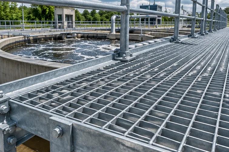
Industrial Walkway Grating Layout
Piece-marked panel assemblies, bearing directions, and support seats.
Applications & Environments
Metal Grating Drawing Applications Across Industrial Projects
A bar grating scope may involve repetitive flat panels or complex custom cutouts. These applications often need different support, edge, lifting and fixing details, so the shop drawing package should follow the actual contract requirements.
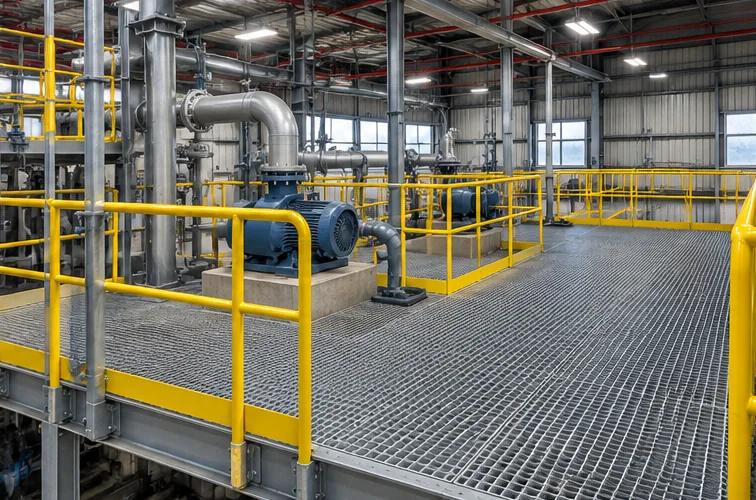
Industrial Platform Grating
Piece-marked panels for raised access platforms, equipment decks and work areas, with support lines and fastening references coordinated to the platform framing.
Plant Walkways and Catwalk Grating
Walking-surface panels for process facilities, treatment works and elevated access routes, including interfaces with guardrails, equipment and openings.
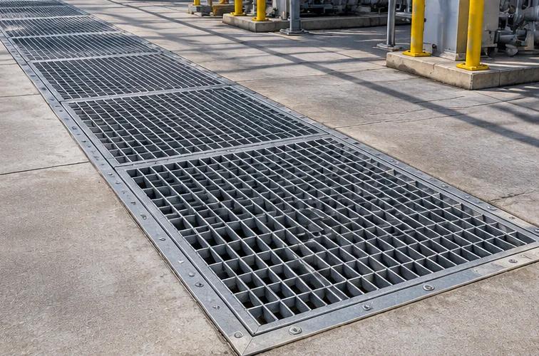
Metal Grating Trench Covers
Removable or fixed panel layouts for floor trenches, drainage channels and service access, with edge frames, panel joints and lifting requirements.
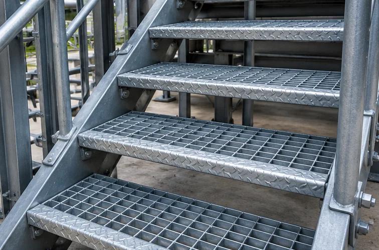
Steel Grating Stair Treads
Defined tread units, nosing or edge treatment, bearing orientation and assembly attachment information for the specified stair system.
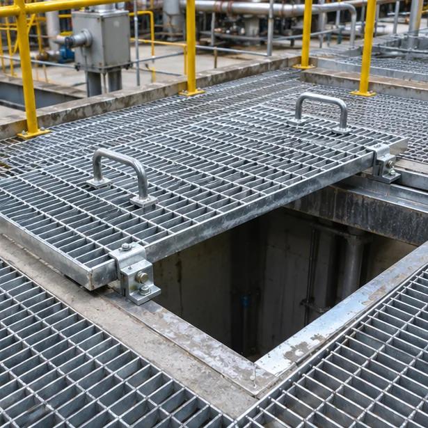
Removable Access Panels
Lift-out grating panels near pumps, valves, hatches or maintenance openings, including identification, support and specified retention hardware.
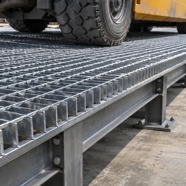
Heavy-Duty Grating Areas
Grating areas identified for specified concentrated, wheel or industrial-service loads. Load capacity remains a design and product-selection responsibility.
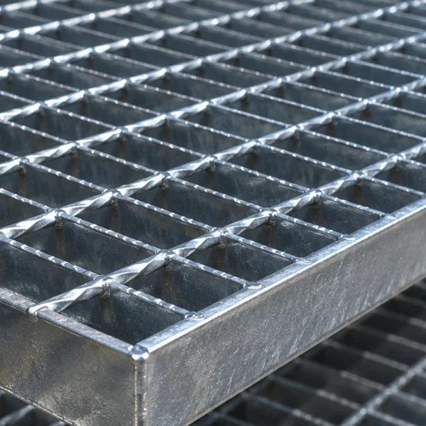
Banded and Custom-Cut Panels
Irregular perimeters, pipe penetrations, corner cutouts, edge banding and special shapes coordinated to existing conditions.
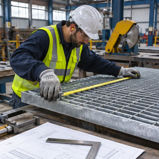
Fabricator-Ready Panel Documentation
Grating parts, piece marks and material references organized for production and project review.
Deliverables Matrix
Typical Metal Grating Drawing Deliverables
The exact deliverable set is defined during quote review. Depending on project scope, a grating package may include the following documentation.
General Layout Plans
The overall grating extents, adjacent building or framing references, panel joints and access routes.
Piece-Marked Panel Plans
Individual panels identified by marks, locations and orientation to match fabrication and field installation.
Bearing-Bar Direction & Supports
Orientation arrows, clear span assumptions supplied by design, seat locations and adjacent support steel.
Cutout, Banding & Edge Details
Penetrations, trim or load banding where specified, notches, clearances and boundary conditions.
Connection & Fastener References
Specified clips, welded connections, bolts, frames or other attachment systems and their locations.
Trench & Removable Panel Details
Access hatches, lifting handles, hinges or specified removable hardware, when included in scope.
Grating Schedules & Material Lists
Panel marks, type, finishes and quantities associated with the supplied product selection.
Submittal & Revision Information
Drawing status, changes, issue dates and other records required for the agreed review process.
Structural Span & Orientation
Why Bearing Bar Orientation Matters in Grating Layout Drawings
Grating panels are directional assemblies. In common metal bar grating, the bearing bars carry the primary load between supports, while the cross bars maintain the assembly's spacing and geometry. Rotating a panel relative to the support steel can change the way the panel spans, so orientation needs to be explicit on the plan.
A useful shop drawing identifies the bearing-bar direction with an arrow and shows the support lines that those bearing bars bridge. The drawing should also distinguish the clear span between effective bearing points from a panel's finished overall size, which may include required bearing and installation clearance.
A plan is incomplete when it labels panels without showing their relation to the support framing. Missing bearing, unclear beam seats, or panel joints placed away from available support should be returned for clarification, not resolved through undocumented assumptions.
Practical Layout Checklist:
Platform Bearing Coordination
Aligning bearing bar spans directly across structural beam centerlines.
Panel Breakdown & Identification
From Platform Outline to Piece-Marked Grating Panels
A grating area on a contract plan may look like one continuous walking surface, while fabrication and delivery require several separate pieces. A layout should document the boundaries and sequence of those pieces without assuming a stock-panel size is suitable for every project.
First, the supporting structure and overall grating extents are reviewed. Next, the panel breakdown is coordinated around fabrication limits, transport and access restrictions, permanent or removable zones, openings and required support. Each unique panel receives a reference mark that is carried into its detail and schedule.
For installations with repeated shapes, grouping identical panels can make a set easier to review. For irregular layouts, panel-specific details help distinguish similar-looking pieces that have different cutouts or edge treatments.
| Drawing Field | What the Fabricator and Installer Need to Identify |
|---|---|
| Panel mark | A unique part reference tied to its sheet and schedule |
| Finished panel size | Project-specific dimensions approved for fabrication |
| Bearing direction | Direction of the primary load-carrying bars |
| Support references | The structural seats or framing members under the panel |
| Edge conditions | Open, trimmed, load-banded or trench-banded treatment where specified |
| Openings | Cutouts with location and clearance references |
| Fastening method | Approved type and documented locations |
| Installation note | Any access, removable zone, revision or field-verification requirement |
Perimeter & Penetration Detailing
Grating Cutouts, Trim Banding and Perimeter Details
Pipe penetrations, columns, cable routes, drains and equipment supports frequently interrupt a grating run. The relevant shop drawings should show each opening in plan, identify its reference to the surrounding panels, and document the applicable edge treatment from the approved project information.
Banding is not one universal detail. Open grating ends, standard trim banding, elevated trench banding and load banding address different fabrication and service needs. The project specifications and selected grating product establish the required condition. If a penetration cuts several bearing bars, the remaining panel and framing condition require review by the responsible design team.
A grating plan should avoid ambiguous notes such as “field cut as required” when the contract demands prefabricated cutouts. Clear marks and coordinated dimensions reduce the likelihood that the installation team receives visually similar panels with different openings.
Welded Edge Banding Detail
Coordinating trim banding, load banding bars, and perimeter clearances.
Attachment & Restraint
Grating Attachment and Support Coordination
Grating panels require suitable retention to the supporting structure. Depending on project specifications and product selection, the attachment may involve mechanical clips, weld lugs, bolted devices, shop-welded components or other approved systems.
The drawing set should indicate which panels are removable, where the specified fixing method applies, and how attachments relate to the bearing support. A generic fastening note is inadequate when multiple hardware types or support conditions occur on the same level.
Connection size, weld requirements, bolt specification, edge bearing and support adequacy must come from the approved product and engineering information. Standard detailing does not authorize a drafter to select new structural fastener capacities or change the design load path.
Mechanical Saddle & G-Clips
Documented clip locations on bearing bars securing panels directly to structural beam flanges without field welding.
Shop & Field Weld Lugs
Weld washer and lug details specified for permanent vibration-resistant platform installations in heavy plant environments.
Clearance & Seat Bearing
Coordination of NAAMM standard minimum 1-inch bearing seats on all perimeter framing angles and intermediate structural beams.
Trench & Pit Drainage
Trench Cover and Access Panel Shop Drawings
Trench covers often look repetitive on plan but include individual panels with different lengths, perimeter framing and clearances. Some are intended for occasional maintenance access, while others are within regular walking routes or specific equipment zones. Those differences should be defined by the actual contract documents.
For removable panels, drawing information may include piece marks, lifting provisions, specified lock or clip devices, panel support frames, and any scheduled panel access order. Hatches or vault covers may also require separate hardware details if included in the scope.
When grating is exposed to wheeled equipment or concentrated traffic, the responsible design professional and product manufacturer must establish the relevant loading and grating selection. A drawing's visual resemblance to heavy-duty grating is not evidence of its load rating.
Trench Drain Grating Panels
Rebate angle seating and segmented panel spans.
Removable Grating Access Hatch
Flush lifting handles and equipment access clearance.
Materials & Finishes
Grating Products and Material Information on Shop Drawings
The project specification governs whether the package calls for welded steel bar grating, stainless steel grating, aluminum grating, heavy-duty bar grating, press-locked products, or another approved system. The drawing should reference the specified designation and construction instead of substituting a generic “metal grate” label.
Surface conditions such as smooth or serrated bearing bars, finish requirements such as galvanizing, and environments subject to corrosion can affect procurement and fabrication. These conditions should be listed in the appropriate panel details or schedules, supported by the specified manufacturer or project documents.
The detailing scope does not independently certify corrosion resistance, slip performance, loading capacity or accessibility. Those requirements are established through approved design and product documents.
Carbon Steel (W-19-4)
Standard welded carbon steel bar grating, hot-dip galvanized per ASTM A123 or mill black painted finish.
Stainless Steel (304 / 316)
Corrosion-resistant bar grating for wastewater treatment plants, chemical processing facilities, and marine settings.
Aluminum Grating (SG / SGI)
Lightweight swaged or pressure-locked aluminum bar grating for water treatment and architectural catwalks.
Heavy-Duty Welded (W-30-4)
Heavy-duty bar grating panels designed for concentrated forklift, truck, or heavy industrial machinery traffic.
Serrated Grating Stair Treads
End carrier plate punching, abrasive nosing, and stringer attachment.
Stair Access Components
Steel Grating Stair Tread Shop Drawings
Grating treads combine a walking surface with an attachment arrangement and specified front-edge treatment. Unlike floor-panel sheets, tread details often require a plan, side elevation, fixing information and a clear relationship to the stair stringers.
Shop drawing information may identify the tread mark, grating designation, tread width, nosing type, end plates or fixing angles, and spacing based on the approved stair design. For identical flights, repeated tread types can be scheduled together while keeping differences between levels and stair runs visible.
This grating page covers tread-level documentation. Overall riser distribution, stair geometry, landing supports and the full stair steelwork package belong on our dedicated Steel Stair Shop Drawings page.
BOM & Cut Schedules
Grating Panel Schedules That Support Fabrication and Installation
A schedule should correspond directly with the layout sheets. When a panel mark appears on the plan, the fabricator should be able to identify the selected product, relevant size information, finish and quantity from its detail or schedule.
A useful panel schedule also helps reviewers identify gaps. For example, a removable panel may have a distinct fixing method, a cutout panel may require special edge banding, and a tread may have a separate nosing specification. Treating all those items as one undifferentiated material line can hide important fabrication decisions.
Schedules should be consistent with the current revisions of both the source drawings and the grating product selections. The final list is project-specific.
Cross-Trade Alignment
Grating Drawings Must Fit the Surrounding Construction
Most grating packages depend on framing or supports designed under another scope. A panel layout should coordinate with the supporting structural steel, concrete edges, equipment openings, pipe penetrations, platform access and guardrail or toe-plate requirements shown in the contract documents.
A common source of rework is an assumed support line that does not exist after a structural revision. Another is a penetration moved by equipment coordination after the panel has been detailed. A third is a removable cover that cannot be lifted because a nearby handrail, equipment frame or overhead service blocks access.
Identifying these interfaces before release is more useful than producing a visually complete sheet with unresolved geometry. For comprehensive platform and catwalk framing detailing, explore our dedicated Steel Platform & Catwalk Drawings service.
Deliverable Previews
Metal Grating Shop Drawing Examples
These six conceptual drawings show the types of plans and details often involved in a grating fabrication package. They are original, illustrative examples created to explain drawing organization. They are not customer project records, stamped engineering, or fabrication-approved documents.
Illustrative drawing samples only. Not for fabrication, construction, engineering design, or compliance verification. All dimensions, materials, loads and attachments require project-specific approval.
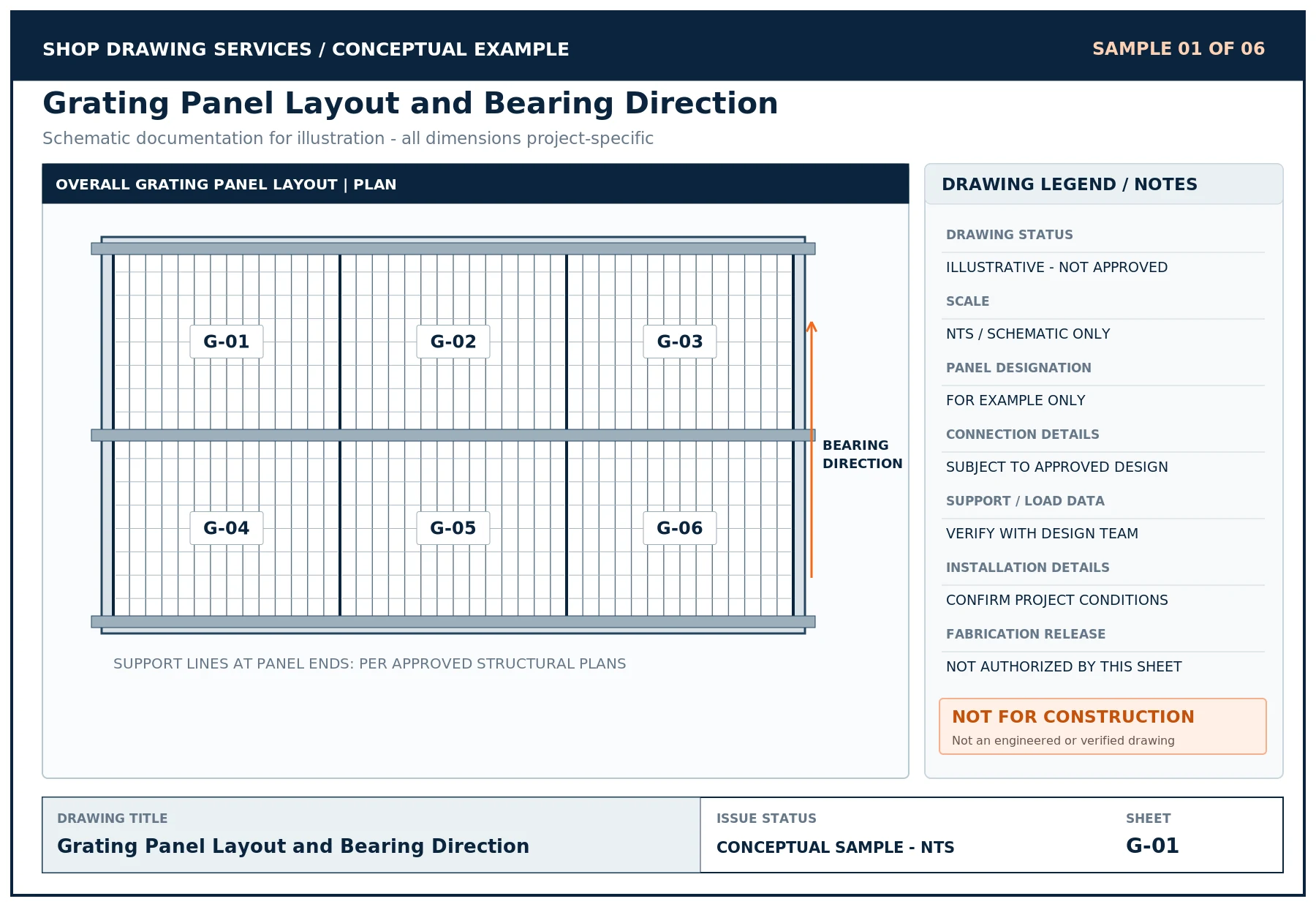
GENERAL PLATFORM LAYOUT & BEARING PLAN
Scale: 1/4" = 1'-0"Grating Panel Layout and Bearing Direction
Shows schematic piece marks, support lines and bearing direction across framing members.
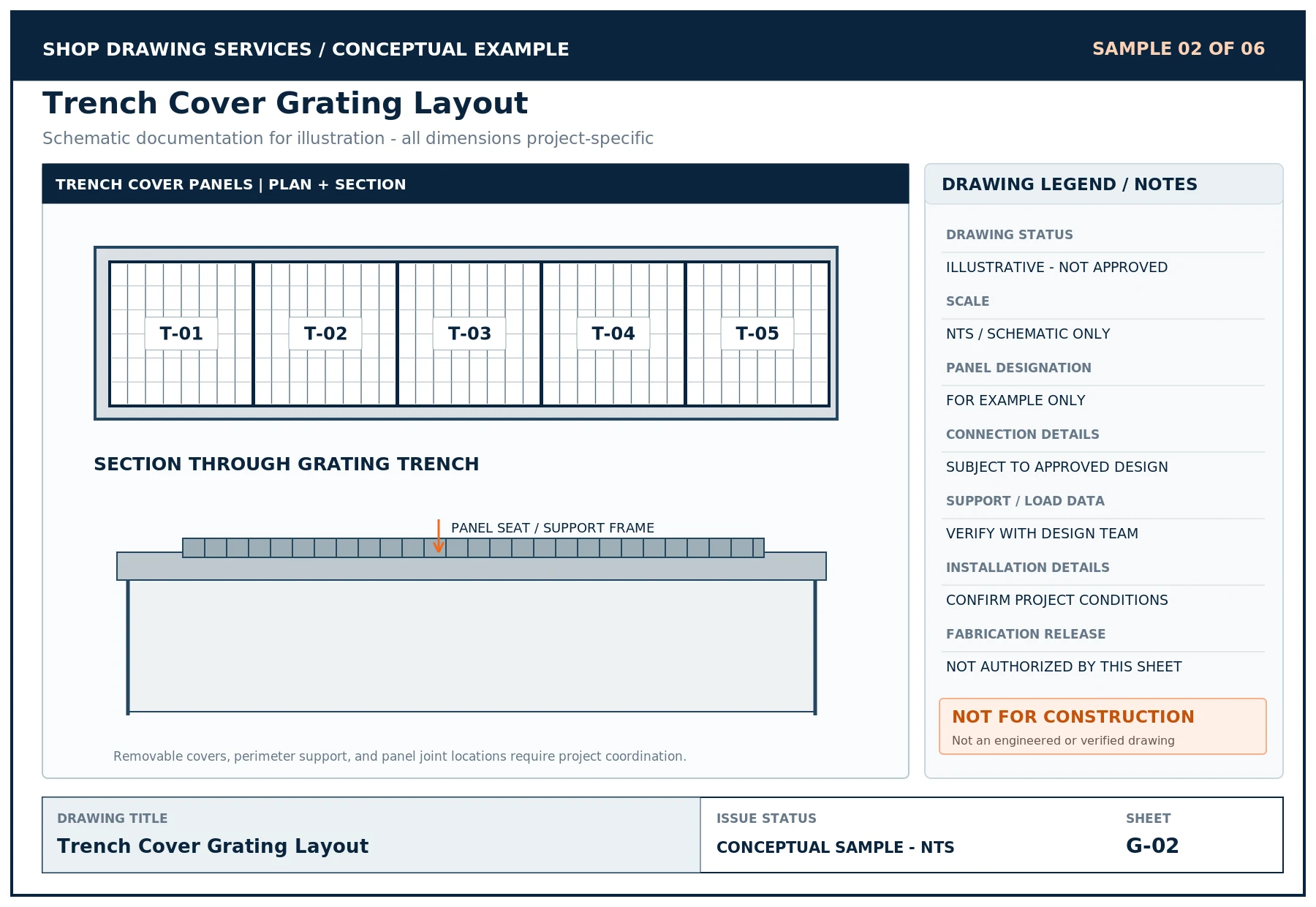
DRAINAGE TRENCH & UTILITY PIT COVERS
Scale: 1/2" = 1'-0"Trench Cover Grating Layout
Illustrates removable trench grating pieces and support section within concrete rebates.
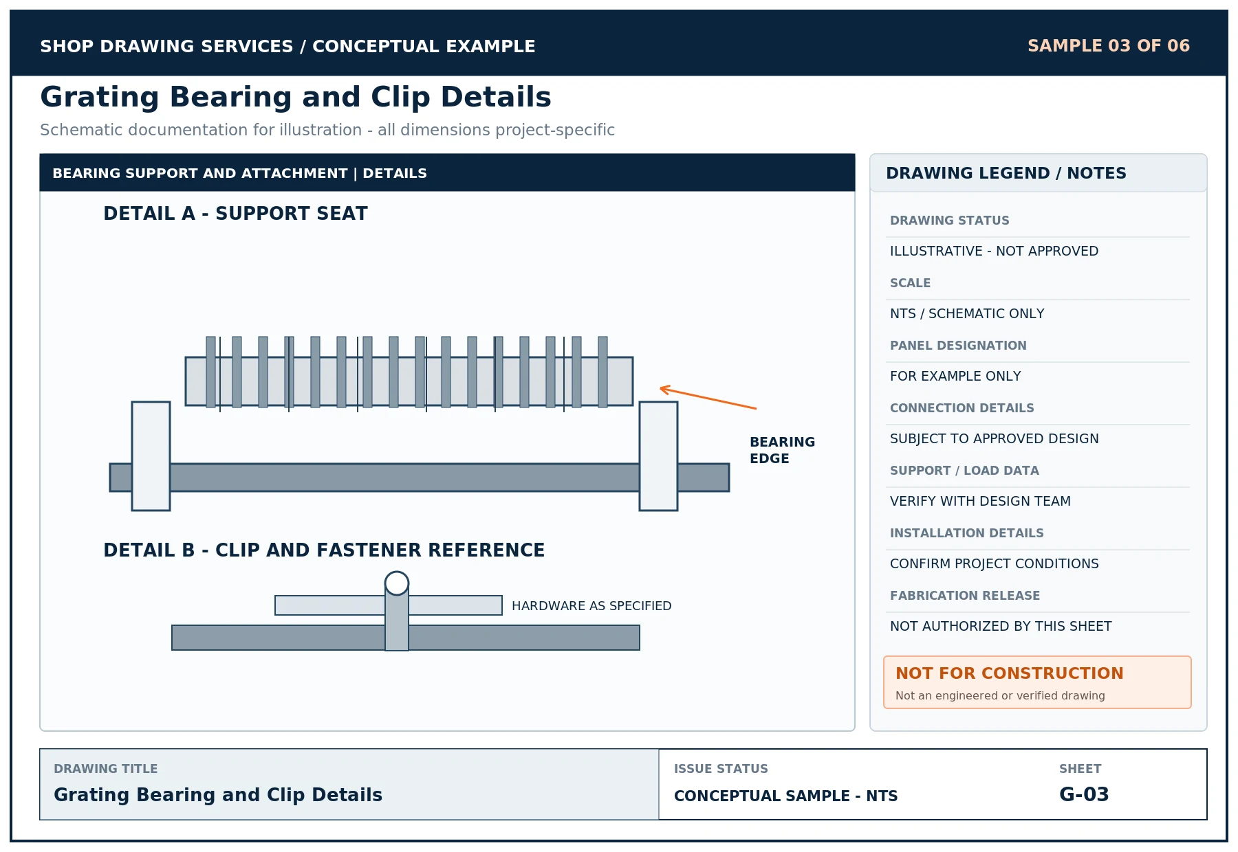
SUPPORT SEATING & FASTENING HARDWARE
Scale: 1-1/2" = 1'-0"Grating Bearing and Clip Details
Shows conceptual support seating, saddle clips and mechanical fastening references.
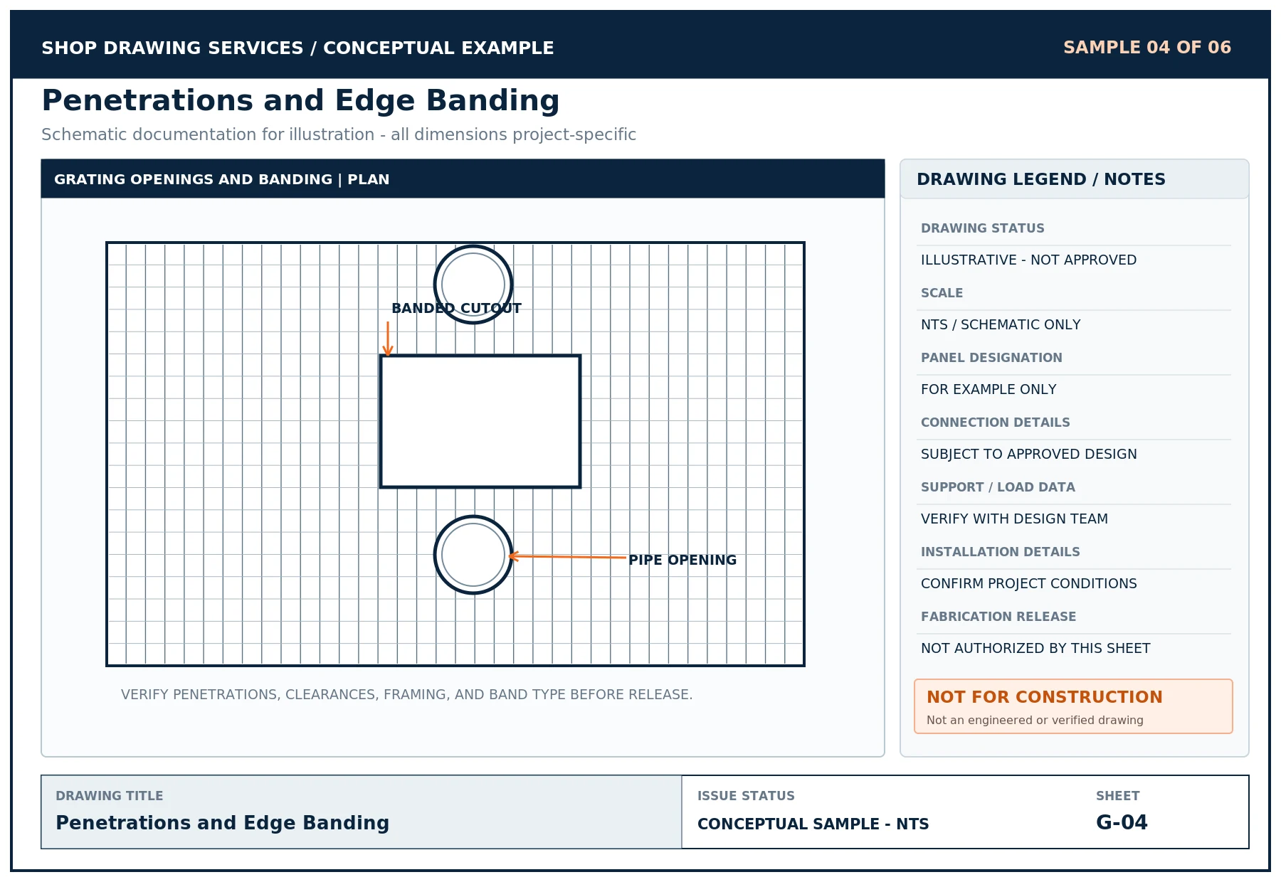
CUTOUTS, NOTCHES & PERIMETER BANDING
Scale: 1" = 1'-0"Penetrations and Edge Banding
Illustrates an opening, cutout clearances and border edge treatment.
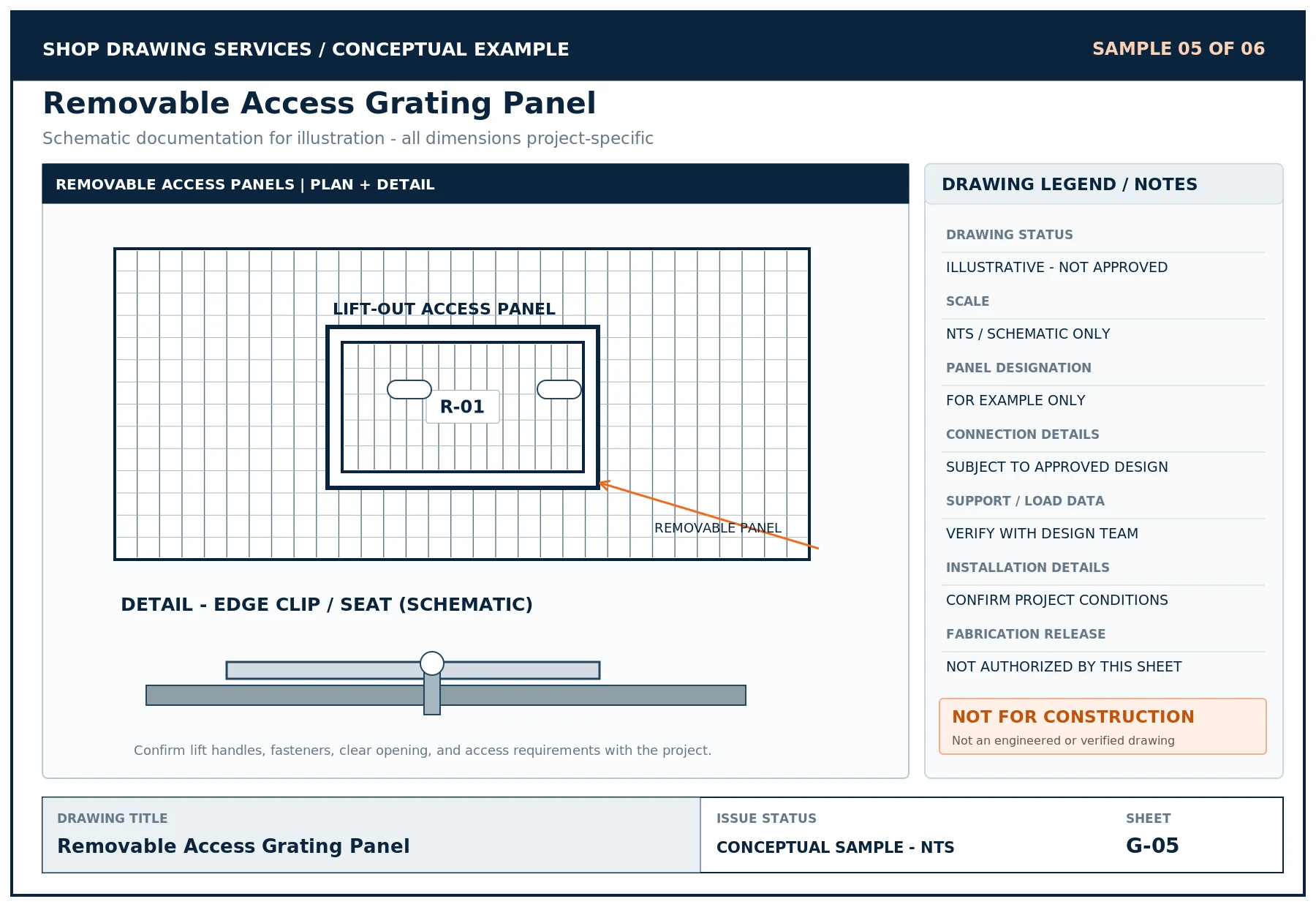
EQUIPMENT HATCH & HINGED ACCESS PANEL
Scale: 1" = 1'-0"Removable Access Grating Panel
Shows a conceptual lift-out panel, recessed lift handles and edge hardware.
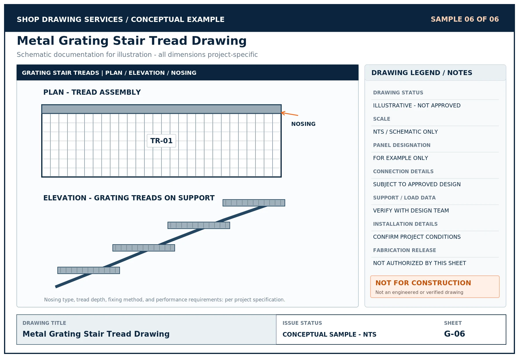
STAIR TREAD ASSEMBLY & SAFETY NOSING
Scale: 1-1/2" = 1'-0"Metal Grating Stair Tread Drawing
Illustrates tread plan, side profile, bolt hole centers and nosing context.
Quotation Preparation
What to Send for a Metal Grating Shop Drawing Quote
A clear scope package lets the detailing work be priced around the actual panels and drawing deliverables. Please include the latest available project documents and note any missing items requiring clarification.
Send your project plans and specifications for a scope-specific grating proposal.
Upload Your PlansWorkflow & Quality Control
From Project Grating Areas to a Coordinated Drawing Set
Review Assigned Scope
Identify the grating locations, current contract documents, applicable specifications, and required drawing outputs.
Confirm Inputs
Review approved material and grating type, supports, bearing directions, openings, attachments and missing information.
Develop Details
Prepare marked panel plans, cutouts, edge information, typical details and related schedules within the confirmed scope.
Coordinate Package
Reconcile drawing marks and schedules, flag unresolved support or interface issues, and prepare the agreed review issue.
Apply Comments
Update affected sheets and revision records when the responsible project team returns authorized submittal comments.
Error Prevention
Drawing Coordination Issues Worth Catching Before Fabrication
| Potential Issue | Why It Matters | Useful Drawing-Stage Response |
|---|---|---|
Bearing bars shown in the wrong direction | The panel may not match the approved support span | Mark the bearing direction and confirm supporting members |
A panel joint lacks a suitable support | Installation or structural support may be unresolved | Coordinate panel division with structural documents |
Cutout not reflected in the mark or schedule | The shop may produce the wrong part | Identify every nonstandard cutout by piece mark |
Incorrect edge treatment | Finished panel differs from specified handling, support or appearance | Record approved banding type by panel or condition |
Removable cover has no access information | Cover removal or service access may be obstructed | Coordinate lift provisions, hardware and clearances |
Attachment detail conflicts with substrate | The field installation method remains unclear | Request an approved connection and support detail |
Older revisions remain in panel schedule | Delivered pieces may mismatch current site geometry | Use consistent issue dates and changed-panel references |
Industry Standards
Metal Bar Grating Standards and Project Responsibilities
NAAMM provides recognized technical guidance for metal bar grating. Depending on the project, relevant publications include ANSI/NAAMM MBG 531-24 for general metal bar grating, MBG 532-24 for heavy-duty bar grating, MBG 534-26 for metal bar grating engineering design, MBG 533-26 for grating welding practices, and MBG 535-25 for standard practice. Always apply the standard and edition actually specified by the project, and confirm the adopted requirements with the responsible designer or fabricator.
OSHA 29 CFR 1910.22 addresses general walking-working-surface conditions, including the ability of workplace surfaces to support their intended loads. OSHA 1910.28 covers certain fall and falling-object protection responsibilities. The applicable safety duties vary by setting. These provisions do not automatically establish the load rating, product selection or code compliance of a particular grating panel just because the sheet displays a similar product.
The service here covers shop drawing preparation and coordination from approved project inputs. Structural calculations, product load selection, licensed engineering, code certification, field inspection, equipment safety planning and professional stamps require separately defined qualified responsibility.
NAAMM MBG
NAAMM Metal Bar Grating Division publications covering manufacturing tolerances, load tables, and welding.
NAAMM PublicationsOSHA 1910.22
Walking-working surface conditions including clean drainage and load-bearing requirements for industrial floors.
OSHA 1910.22 StandardOSHA 1910.28
Duty to have fall protection and falling-object protection around platform perimeters and floor openings.
OSHA 1910.28 StandardStakeholders & Trades
Grating Drawing Support for Fabricators and Construction Teams
Manufacturers & Fabricators
Need identified panel shapes, cutouts, edge details and schedules to align drawing release with the ordered grating product.
Steel & Misc Metal Subcontractors
Need grating layouts that coordinate with support steel, stairs, access platforms and installation interfaces.
General Contractors & PMs
Use drawing submissions to track scope, clarifications, revisions and coordination with related trades.
Industrial Plants & Facilities
Often need maintenance-access layouts, clear identification of removable panels and records of equipment openings.
Pricing & Project Timelines
What Affects the Cost of Metal Grating Shop Drawings?
Metal grating drawing effort varies with the number of unique panels, irregular geometry, support complexity, cutout quantity, removable panels, selected products, required digital outputs and completeness of project information. A repetitive platform with a clear grating schedule is not the same drawing scope as an industrial retrofit with pipe penetrations, many panel marks and field verification requirements.
The quote should define the agreed panel scope, deliverables, source revisions and expected review cycles. For contractors preparing a wider project budget, our related resource on construction estimating and quantity takeoffs covers a different part of preconstruction work.
Common Questions
Metal Grating Shop Drawings FAQs
Clear answers regarding panel layouts, bearing directions, cutouts, schedules, and deliverables.
Need Metal Grating Shop Drawings for Your Project?
Share your latest grating areas, structural support plans, material specifications and requested deliverables. We will review the assigned drawing scope and prepare a project-specific quotation.