
Steel Stair Shop Drawings for Fabricators & Contractors
Steel stairs require more than an overall plan and a few dimensions. Our steel stair shop drawing services organize stair flights, stringers, treads, landings, support conditions, rail interfaces and fabrication details for the agreed project scope. Share your architectural and structural documents so the assembly requirements and deliverables can be reviewed before a project-specific quotation is issued.
Core Detailing Capabilities:
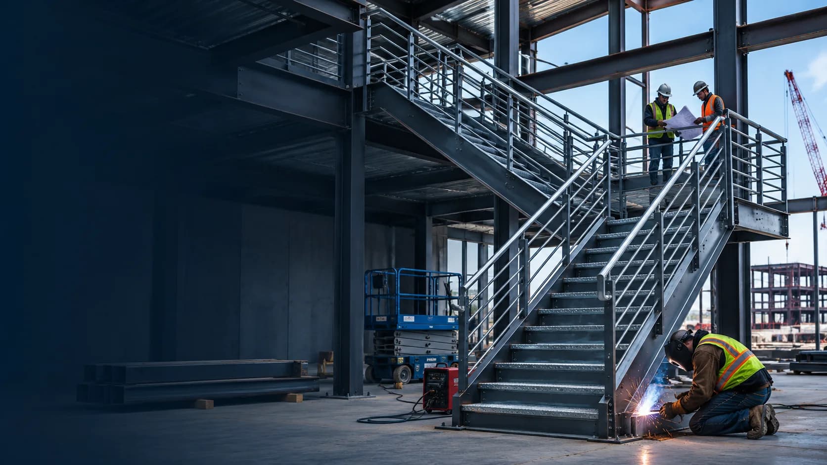
Stair Flight & Stringer Detailing
Custom channel stringers, pan treads, landing framing, and wall returns detailed to contract specifications.
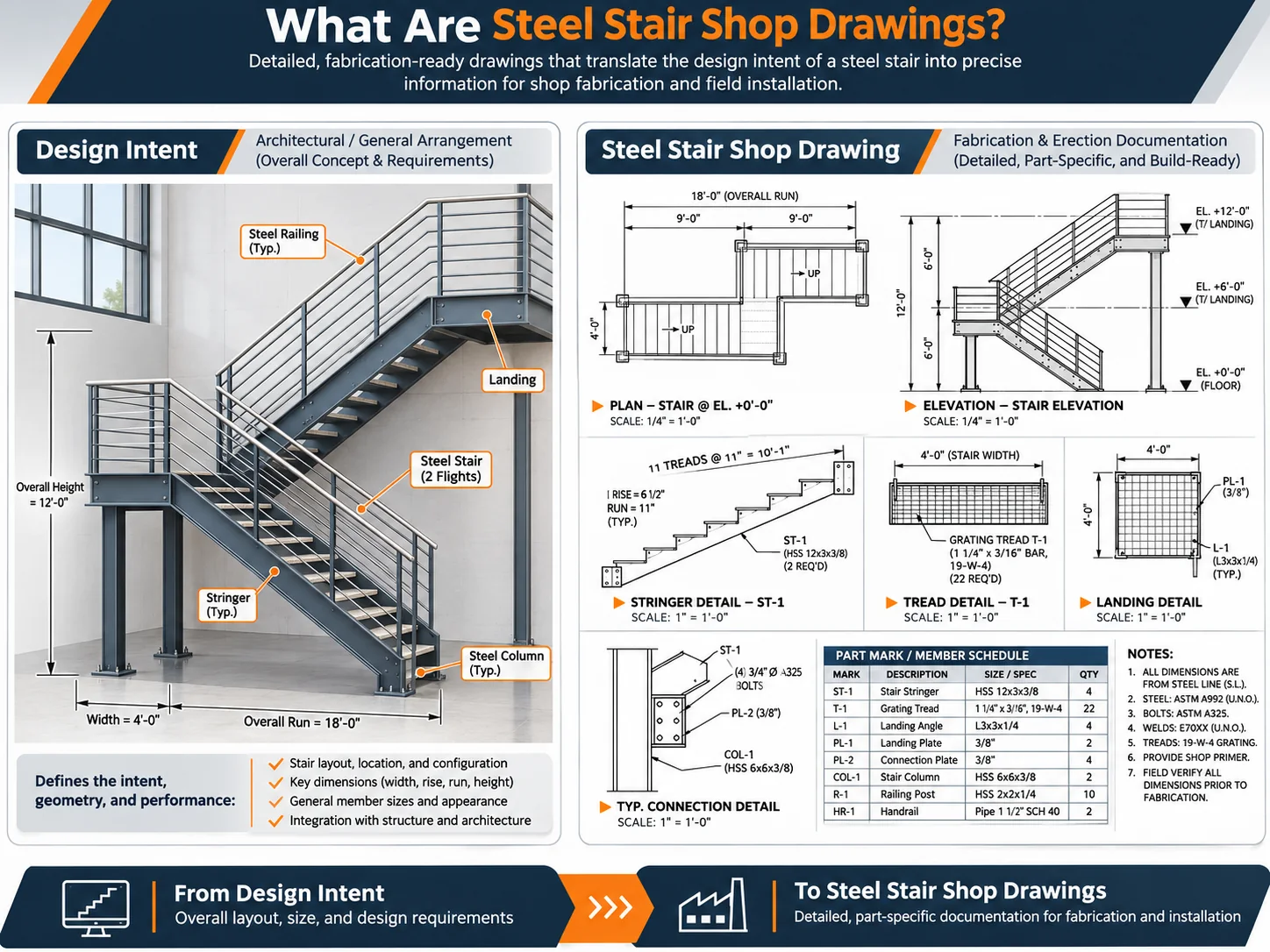
Design Intent vs. Shop Fabrication Drawings
Translating architectural intent into shop-ready cutting, fitting, and assembly sheets.
Scope & Geometry
What Are Steel Stair Shop Drawings?
Steel stair shop drawings develop fabrication and assembly information from the approved architectural and structural design documents. Depending on project scope, they identify flight and landing geometry, stringer profiles, tread construction, support locations, connection references, materials and part marks.
Architectural stair plans establish the intended arrangement and requirements. Structural documents identify relevant supporting conditions and engineering information. Stair shop drawings organize the additional component-level details needed for the agreed fabrication scope, while showing uncertainties that need design-team or contractor clarification.
Consistency between views is important. A change in finished-floor elevation or stair opening dimension can affect the flight layout, stringer end connections, landings and adjacent railings. Revision tracking helps keep the approved source drawings and fabrication sheets aligned.
Stair Configurations
Steel Stair Types We Support
Stair geometry, tread materials, rail interfaces and structural support conditions differ across projects. These common types illustrate the range of stair-specific detailing requests.
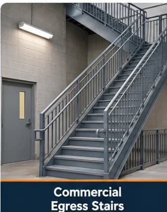
Commercial Egress Stairs
Multilevel flights and landings coordinated with the architectural arrangement, building levels and support structure.

Industrial Access Stairs
Access to platforms, plant levels and equipment, with workplace-specific interfaces and specified components.
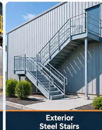
Exterior Steel Stairs
Exposed assemblies with finish, drainage, support and envelope coordination.
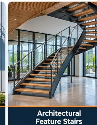
Architectural Feature Stairs
Visually exposed stairs requiring close attention to fabrication and finish interfaces.
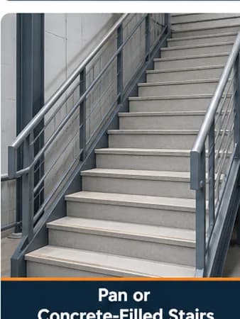
Pan and Concrete-Filled Stairs
Steel stair pans, associated nosing and tread supports based on the selected infill system.
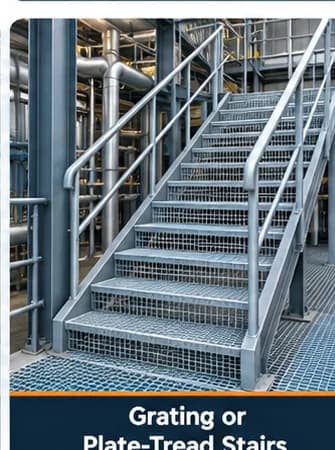
Grating and Plate-Tread Stairs
Specified grating or plate tread assemblies and their fastening details.
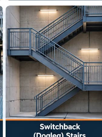
Switchback and Dogleg Stairs
Multiple flights connected through landings, with coordinated vertical geometry.
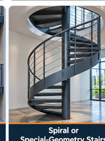
Spiral or Special-Geometry Stairs
Complex assemblies needing separately defined design and engineering responsibilities.
Need broader specialty metal assemblies beyond stairs? Explore our Miscellaneous Metals Detailing Services or primary Structural Steel Detailing Packages.
Deliverable Scope
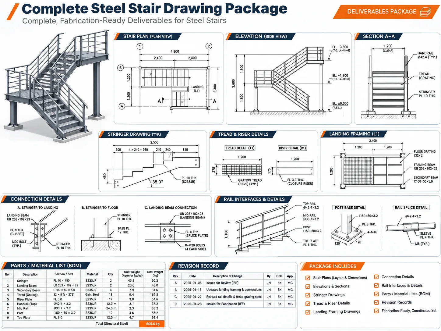
Complete Steel Stair Drawing Package
A steel stair package should help the fabricator, reviewing design team and project contractor locate the information relevant to their work. The exact deliverables depend on contract scope.
| Deliverable | Typical information | Purpose |
|---|---|---|
| Stair plans | Location, flight direction, widths, openings and landings | Coordinate the stair with the building |
| Elevations and sections | Levels, flight geometry, stringer outline and supports | Reconcile vertical relationships |
| Stringer drawings | Section profile, cuts, tread supports, plates, holes and marks | Identify primary fabricated components |
| Tread and riser details | Specified pans, plate or grating, nosing and attachment | Document individual tread assemblies |
| Landing framing | Support members, panels and bearing conditions | Coordinate landing construction |
| Connection details | Approved plates, bolts, welds, anchors and interfaces | Clarify stair-to-building attachment |
| Rail interfaces | Associated rail/post/bracket locations within assigned scope | Reduce fit-up conflicts |
| Parts and material lists | Marks, material, sizes and quantities when contracted | Support fabrication organization |
| Revision records | Issue dates, changed views and replacement sheets | Prevent use of superseded information |
Optional models, CNC data or engineered connection calculations are not automatically part of every package. State inclusions explicitly in the quote.
Coordinated Submittal Organization
Arrangement plans, stringer cutting profiles, and anchor coordination structured for rapid engineering review.
Dimensional Verification
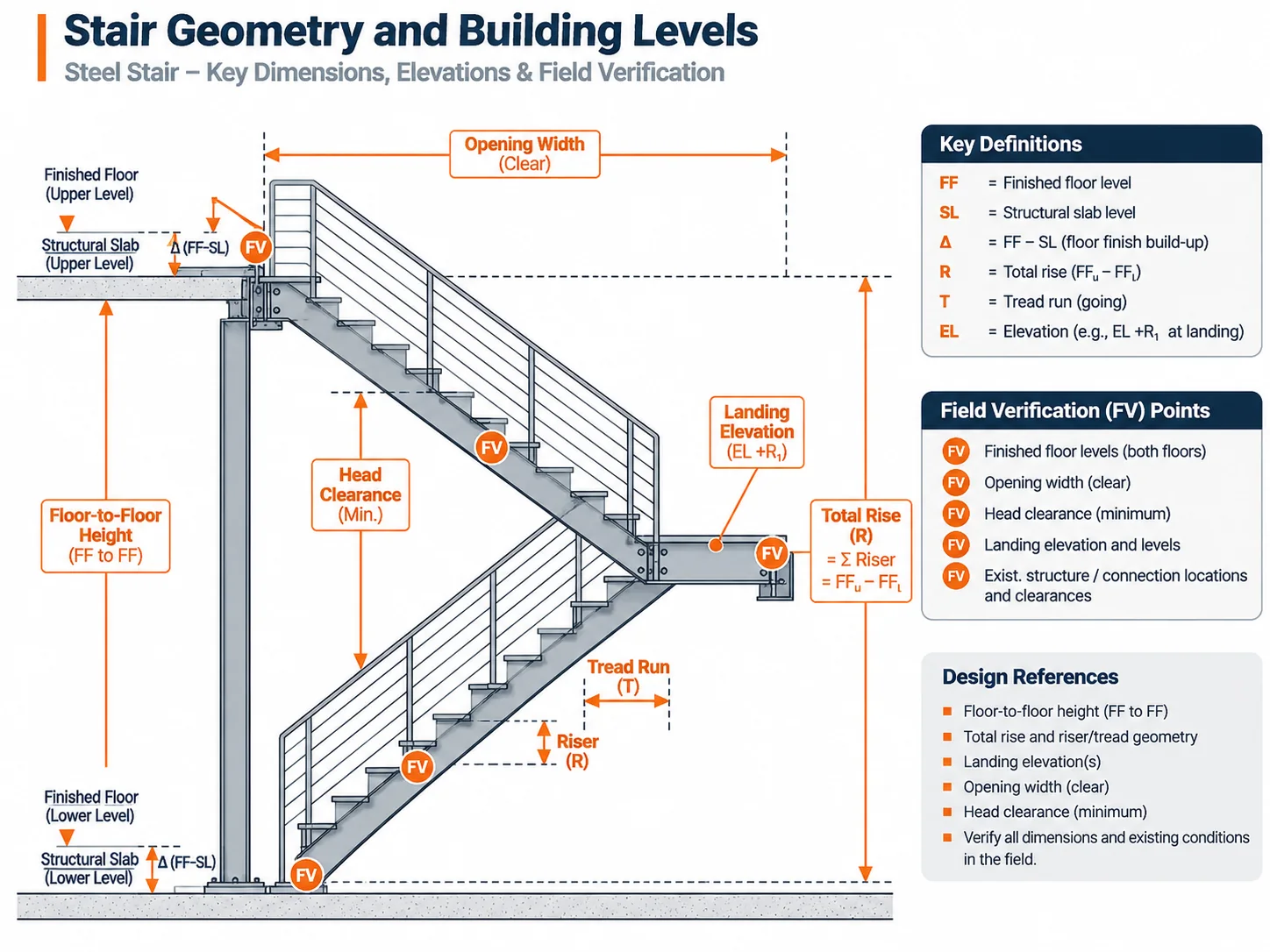
Stair Geometry and Building Levels
Steel stair geometry depends on accurate architectural, structural and field information. Finished-floor elevations and structural support levels are not always interchangeable. A floor finish change can affect the final rise distribution and landing elevations even when the supporting steel is unchanged.
A coordinated set should identify stair locations, flight direction, overall height, landing levels, required clearances and any dimensions that still require field verification. Existing-building work often requires measured conditions rather than assuming the architectural drawing reflects the constructed substrate.
Relevant code criteria must come from the project design and applicable jurisdiction. A detailer should flag inconsistencies, not independently substitute assumed compliant dimensions.
Verification Checklist:
Shop Manufacturing
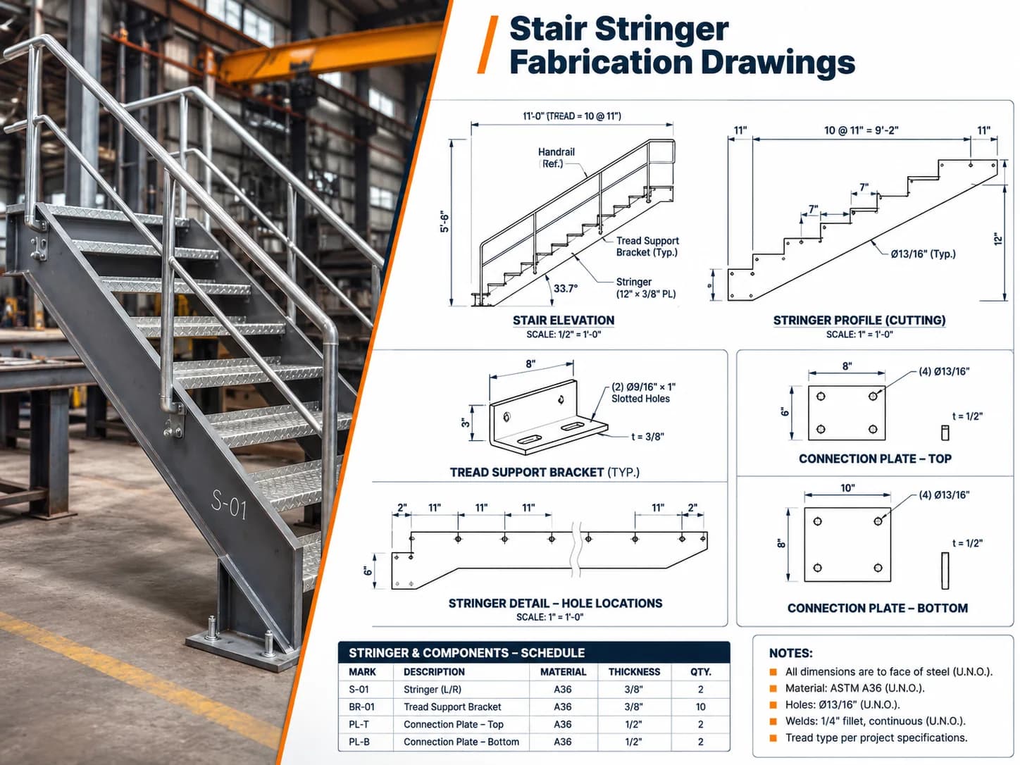
Stair Stringer Fabrication Drawings
Stringers typically form the primary longitudinal members supporting a stair flight. Their fabrication views may identify profiles, end cuts, splices, tread support brackets, plates, hole patterns, piece marks and shop-versus-field work.
Two flights that look alike on a general stair plan may still differ in end connections, floor elevations or nearby wall finishes. The drawings should reconcile those differences before a repeated component is released for fabrication.
The chosen tread system affects the stringer details. Pan treads, plate treads and grating systems require different support and fastening information. Engineering design criteria and connection capacities must be supplied or approved by the responsible professionals when required.
Tread & Riser Assembly
Tread, Riser and Nosing Details
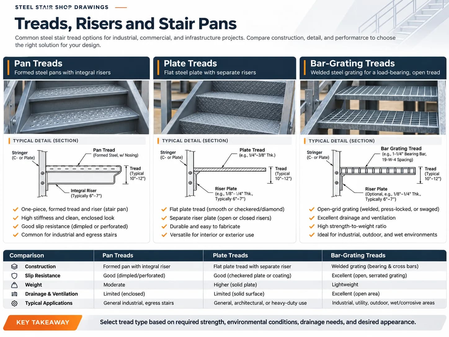
Tread and riser details should represent the actual specified product and assembly. Pan stairs need coordinated infill and final walking-surface information. Grating treads require the relevant support and fastening arrangement. Plate treads may use separate brackets, nosings or surface treatments.
The detail package should indicate the selected system, major geometry, connection references and finish requirements. No standard tread detail fits every occupancy or workplace application. The responsible design team and applicable codes determine the required criteria.
Pan Treads
Formed steel pans for concrete pour with integral nosing angles.
Plate Treads
Diamond checker or smooth steel plate with welded end carriers.
Grating Treads
Bar grating panels with cast abrasive safety nosings.
Structural Interface
Stair Landing Framing and Supports
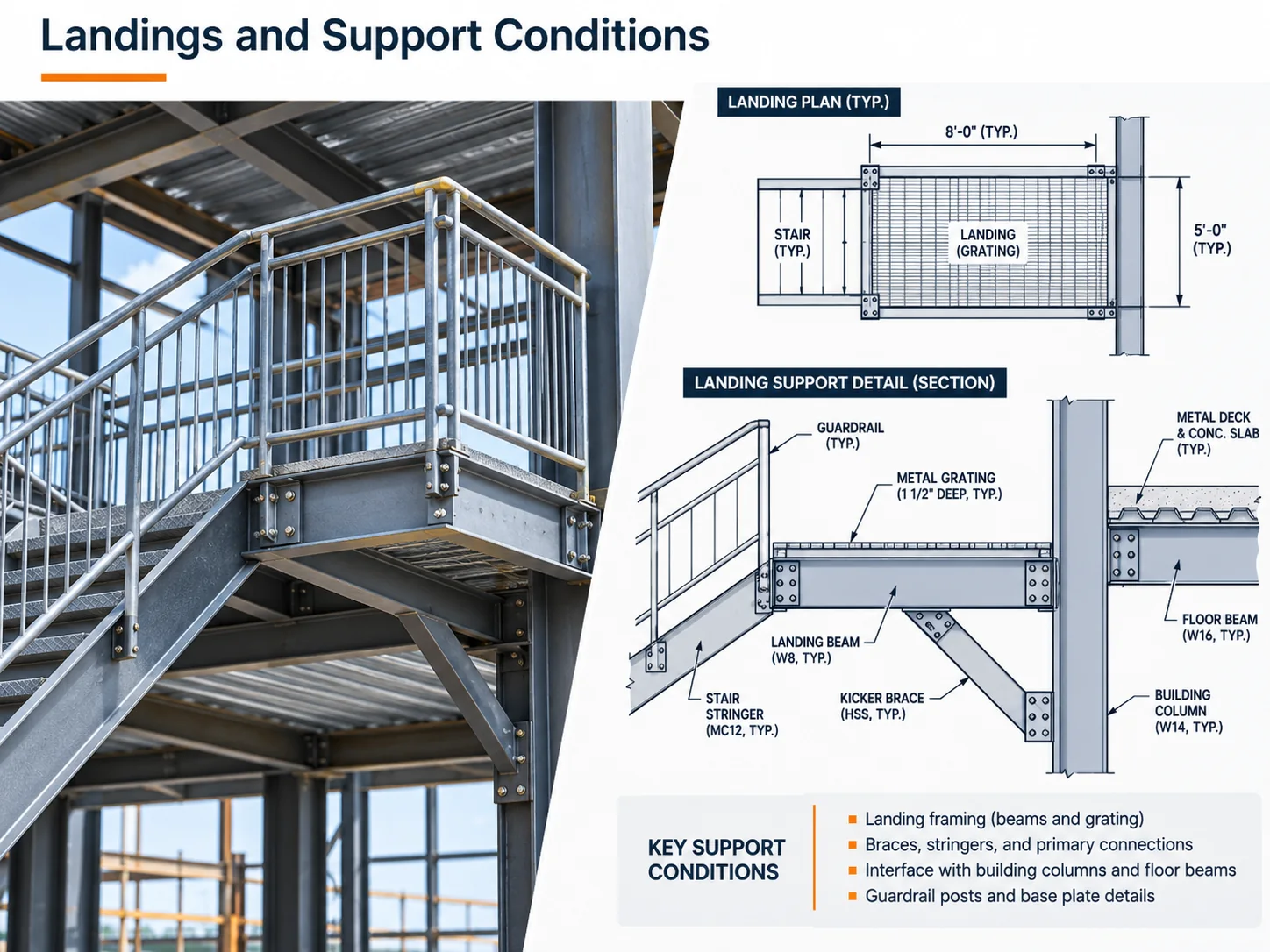
Landings connect flights to one another and transfer the stair assembly into adjacent construction. Depending on design, documentation may show support beams, ledgers, hangers, posts, decking or grating, connection locations and elevations.
A landing that aligns with the shop model can still conflict with a door opening, wall finish, slab edge or embedded plate. Coordinating architectural and structural source drawings before completing the fabrication package helps bring these conflicts into the review process.
The drawing describes the authorized construction details. Structural support design and connection engineering remain the responsibility of the appropriately qualified project parties.
Attachment Coordination
Handrail and Guardrail Interfaces
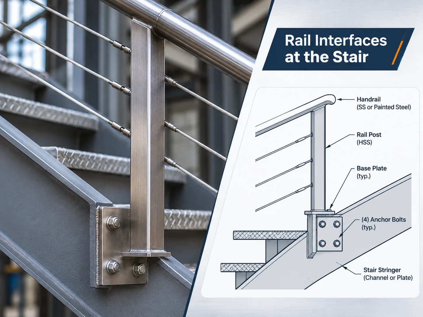
Stair rails and handrails frequently attach to stringers, landing edges or surrounding structural members. Even when railing fabrication is a separate subcontract, stair drawings may need to show the agreed interface points and attachment zones.
Potential coordination topics include post locations, bracket alignment, landings and turns, wall finishes, rail terminations and access clearances. Detailed panel fabrication belongs to the separately contracted rail package where applicable.
Requirements vary with the use of the stair and the applicable building, accessibility and workplace rules. Confirm design criteria through the project documents rather than relying on generic illustrations.
Building Tie-In
Top and Bottom Stair Connections
Steel stairs may connect to structural steel beams, concrete floors, embedded plates, ledgers or designated support brackets. The detailing package should show approved connection geometry and references relevant to fabrication and installation.
Potential information includes connection plates, field bolts, shop weld references, anchor locations and bearing conditions. Missing anchor designs, substrate conflicts or changed structural support information should be raised for clarification before fabrication release.
Connection specifications—including bolt grades, weld sizes, anchor embedment, and engineering calculations—must be provided in the approved design documents and verified by the designated project engineer.
Sample Submittal Sheets
Sample Steel Stair Shop Drawings
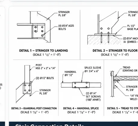
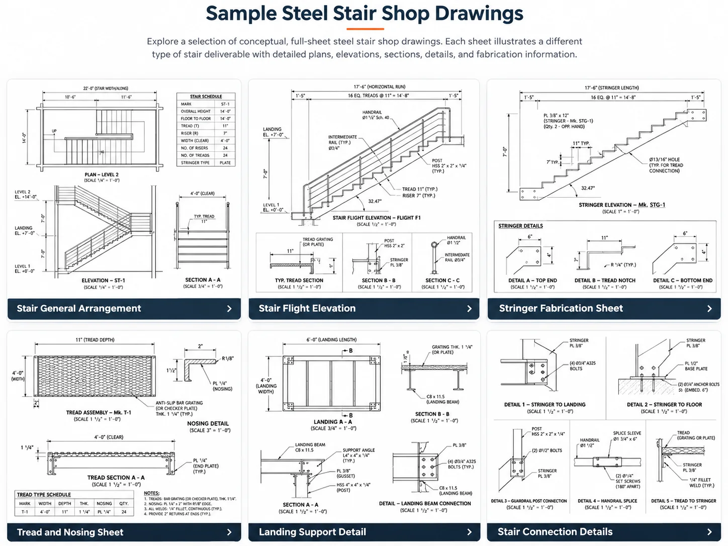
The following conceptual drawing types illustrate the organization of a stair fabrication package. They are not actual completed customer projects or approved construction documents.
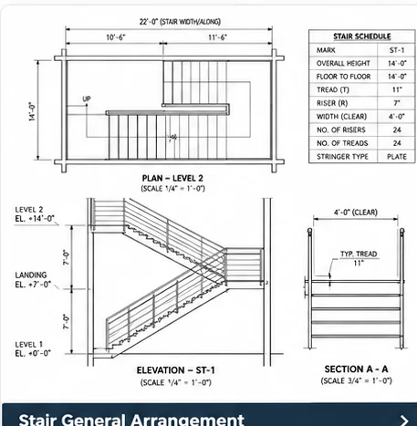
STAIR GENERAL ARRANGEMENT
Scale: 1/4" = 1'-0"Stair General Arrangement
Overall flights, landings and building references coordinating the stair assembly with the surrounding structure.
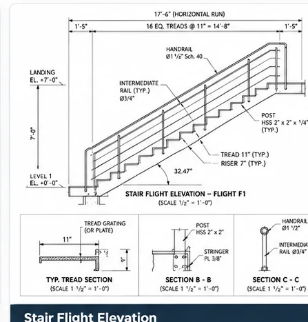
STAIR FLIGHT ELEVATION & SECTION
Scale: 1/2" = 1'-0"Stair Flight Elevation
Side elevation, levels and stair geometry reconciling vertical riser distributions and landing transitions.
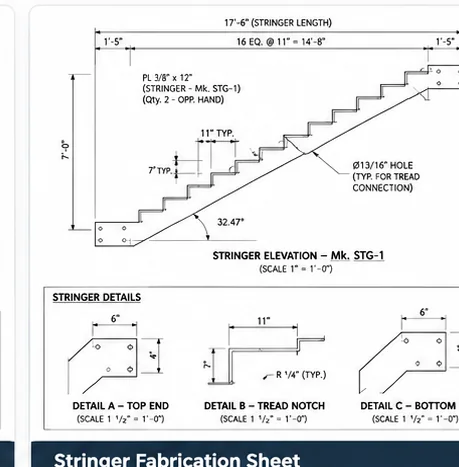
STRINGER FABRICATION DETAILS
Scale: 3/4" = 1'-0"Stringer Fabrication Sheet
Member profile, connections and tread supports documenting cut lengths, hole patterns, and weld points.
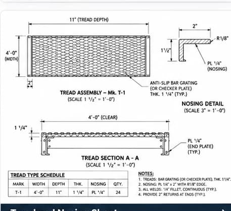
TREAD & NOSING DETAILS
Scale: 1-1/2" = 1'-0"Tread and Nosing Sheet
Pan, plate or grating detail examples showing tread construction, nosing profiles, and fastening methods.
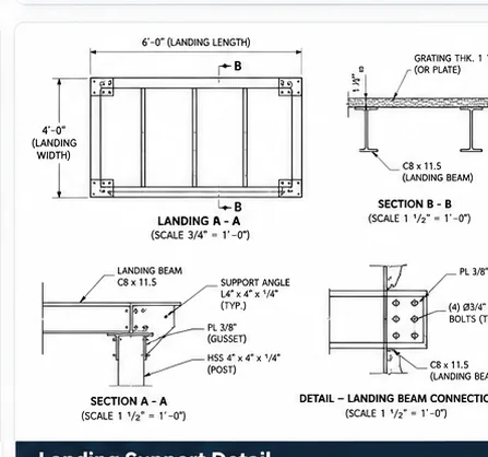
LANDING FRAMING & SUPPORTS
Scale: 3/4" = 1'-0"Landing Support Detail
Framing and attachment interfaces detailing landing beams, hanger rods, posts, and wall ledger connections.
STAIR-TO-STRUCTURE CONNECTIONS
Scale: 1" = 1'-0"Stair Connection Details
Conceptual top/bottom connection views showing approved plates, anchors, bolts, and structural interface geometry.
Quotation Preparation
What to Send for a Steel Stair Shop Drawing Quote
Provide relevant documents to define the stair assemblies and required deliverables:
If the project contains many stair runs, mark the exact flights and levels included in the quote request. Missing information should be identified before confirming scope and schedule.
Submittal Documentation
Flight elevations, stringer cuts, and landing plates prepared for rapid engineering review.
Workflow & Coordination
How Our Stair Detailing Process Works
A systematic 5-step workflow ensuring strict alignment between architectural design intent and shop manufacturing requirements.
Scope Review
Identify stair runs, source drawings, specifications, assembly types and requested deliverables.
Clarifications
Flag missing levels, openings, connections, finishes and relevant field-condition questions.
Drawing Preparation
Develop arrangements, stringers, tread/landing details and agreed schedules.
Checking and Submission
Reconcile related views, part marks and revisions before issue for the agreed review stage.
Authorized Revisions
Incorporate documented review comments and supply the agreed final issue files.
The reviewing design team and contractor retain their assigned review, approval and construction responsibilities.
Proactive Coordination
Common Stair Detailing Conflicts
Early identification of geometric and structural discrepancies prevents expensive rework during shop fabrication and jobsite installation.
| Coordination problem | Possible effect | Drawing-stage response |
|---|---|---|
| Finish floor differs from structural slab level | Changes riser distribution and landing geometry | Confirm design elevations |
| Openings differ between architectural and structural plans | Stair clearance or fit-up conflict | Reconcile drawings and field conditions |
| Landing support is undefined | Incomplete attachment details | Request approved support design |
| Rail posts interfere with stringer brackets | Assembly or installation conflict | Coordinate component locations |
| Tread product changes after detailing begins | Reworked tread and bracket sheets | Confirm selected product and revision |
| Old addenda remain in use | Inconsistent fabricated components | Track current issue information |
| Anchors or weld requirements are missing | Cannot complete approved connection sheet | Request engineering clarification |
Codes & Standards
Applicable Standards and Responsibility Boundaries
Steel stairs are used in different contexts, and their governing requirements are not interchangeable. Permanent building egress stairways may be governed by the locally adopted International Building Code and relevant accessibility standards. Covered general-industry workplace stairways have OSHA 1910.25 provisions, while OSHA 1926.1052 addresses stairways within construction activity. The applicable edition, occupancy, jurisdiction and project specifications must be identified for each job.
AISC 303 addresses standard practices for structural steel contracting within its scope, but is not universal proof that a stair assembly meets every relevant code. Project-specific materials, welding and structural connections must reflect approved design documents.
The service described here covers drawing preparation and coordination. Professional engineering design, delegated calculations, signed plans, safety-plan preparation, inspections and final approval require separately defined qualified responsibility. Illustrative samples must never be used as fabrication instructions.
Governing Technical Reference Sources:
Structural steel contracting practice and document scopes.
Industrial stair widths, angles, treads, and riser tolerances.
Site safety requirements for temporary and permanent stairways.
Egress geometry, riser heights, tread depths, and landings.
Accessible stair nosings, handrail extensions, and clearances.
Deliverables & Compatibility
Drawing Formats and Optional Outputs
PDF sets support common submittal review and issue tracking. Depending on the confirmed scope and company workflow, editable DWG or DXF, relevant 3D models, material schedules or other agreed digital outputs may also be included.

Vector PDF
Submittal Booklets & Shop Prints

AutoCAD .DWG
Editable 2D CAD Layouts

DXF Profiles
Plate & Component Profiles

IFC 3D BIM
Open BIM Model Coordination

3D Isometric Views
3D Perspectives & Visuals

CSV / Excel Schedules
Material & Cut Lists
Review the complete software platforms we support on our Supported Detailing Software Page.
Estimating & Turnaround
Pricing and Turnaround Factors
Steel stair shop drawing effort depends on the number of flights, uniqueness of assemblies, stair geometry, tread and railing interfaces, support complexity, quality of source drawings, required 3D modeling and expected revision cycles. A repetitive industrial stair with complete source details is a different task from a multilevel feature stair with complex exposed connections.
Accurate quotations start with a clear stair list, updated drawings, specifications, delivery expectations and required file formats. Project proposals reflect your specific scope, assembly complexity, and timeline requirements.
For broader project budgeting, contractors may reference construction cost estimating services when reviewing project quantities and cost assumptions. This is a contextual external resource, not another stair detailing service.
Key Estimating Variables:
Project Stakeholders
Who Uses These Drawings?
Steel fabricators use assembly and individual component information to organize production. General contractors use shop drawings for scope and submittal coordination. Steel stair subcontractors need drawings that reflect their assigned fabrication and installation scope. The project's architects and engineers review submitted information under the applicable contract.
These services are relevant to commercial offices, warehouses, industrial plants, multifamily buildings, schools, healthcare facilities and renovation projects.
Steel Fabricators
Use assembly and individual component information to organize shop cutting, punching, fitting, and welding.
General Contractors
Use stair shop drawings for multi-trade scope, slab opening alignment, and submittal coordination.
Stair Subcontractors
Need accurate fabrication sheets that reflect their assigned contract scope and field erection tolerances.
Architects & Engineers
Review submitted dimensional information, materials, and connection configurations under the contract.
Working as a prime contractor? Visit our dedicated General Contractors Detailing Hub or browse all Construction Industries We Support.
Common Questions
Frequently Asked Questions
Clear answers regarding stair detailing scopes, submittal packages, stringers, treads, and project reviews.
A drawing set may include stair plans, elevations, stringers, treads, landing framing, approved connections, associated rail interfaces, schedules and revisions. Scope is confirmed before work begins.
Have a question not addressed here? Check our comprehensive Sitewide Detailing FAQ Center or contact our team directly.
Start Your Drawing Submittal
Need Steel Stair Shop Drawings for Your Next Project?
Send your latest architectural drawings, stair schedules and structural support details to receive a scope-specific drawing proposal.