

Metal Ladder Shop Drawings for Fabricators & Contractors
Steel ladders need clear fabrication information and reliable coordination with the structures they connect to. Our metal ladder shop drawing services organize fixed ladder layouts, side rails, rungs, support brackets, landing interfaces and approved attachment details for industrial and commercial construction. Send your current project drawings and scope requirements for a tailored detailing quotation.
Detached Detailing & Drawing Coordination
Fixed Ladder Shop Drawings That Connect Design Intent to Fabrication
Metal ladder shop drawings turn an approved project ladder design into a set of documented components and assembly relationships. For a fixed ladder, the package may identify the ladder's assigned location, intended climbing height, side-rail profiles, rung arrangement, mounting brackets, attachment substrates, top access configuration and relevant material or finish references. The drawing set gives the fabricator a consistent view of how the specified ladder components fit together and where unresolved project information must be clarified.
A construction drawing may show a ladder symbol and an elevation while leaving fabrication choices and support interfaces to later coordination. The shop drawing stage organizes those details according to the assigned scope. Depending on the project, a small wall-mounted ladder requires a different drawing set from a tank-access ladder with multiple supports, a platform transition and a specialist ladder safety system.
The service described here is detailing and drawing coordination, not automatic structural design, fall-arrest system engineering, installation or independent code certification. Fabrication drawings rely on the project's approved design information and applicable specifications.
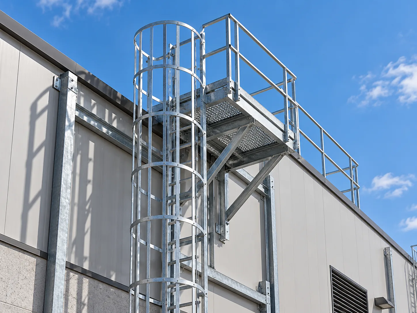
Galvanized Fixed Ladder Installation
Exterior commercial roof access showing standoff brackets and walk-through handrails.
Access Categories & Exposure
Metal Ladder Drawings for Industrial and Commercial Access
Fixed ladders appear across maintenance, roof access, plant equipment, storage and utility projects. Their geometry, connections, exposure and access conditions differ by application. Confirm the exact ladder types and quantities in the scope before requesting shop drawings.
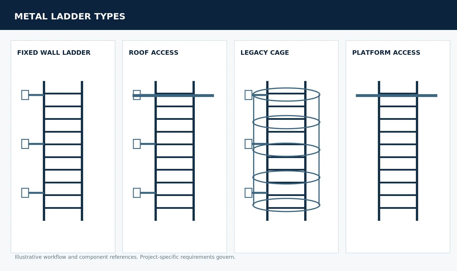
Figure 3.1: Common Fixed Ladder Types, Wall Standoffs, and Upper Landing Configurations
Fixed Wall Ladders
Structural StandoffsPermanent ladders mounted to a structural wall, frame or other approved support. Shop drawings document the ladder rails, rung layout, wall-bracket interfaces, component marks and mounting relationships. The approved substrate and fastening design are essential inputs.
Roof and Hatch Access Ladders
Walk-Through ExtensionsFixed ladders serving a roof, hatch or elevated access point. Drawings identify the ladder arrangement relative to the opening, roof edge, guard, gate or handhold and establish which dimensions require field verification. Top transitions must coordinate with the actual architectural and structural details.
Tank and Equipment Access Ladders
Industrial EquipmentLadders used to reach industrial equipment, tanks or elevated maintenance areas. Drawings may include curved or offset support references, bracket interfaces, adjacent piping and platform alignment. Equipment-related work may also require manufacturer requirements and plant-specific access criteria.
Ladder-to-Platform Access
Catwalk InterfacesFixed ladders connecting to platforms, catwalks or elevated walkways. The transition needs consistent references for elevation, step-across, guard openings, access gates and the support steel. Drawings should clearly distinguish ladder fabrication from work assigned to the platform or guardrail contractor.
Deliverables Matrix
What a Metal Ladder Fabrication Drawing Package May Include
The deliverable list depends on the contract and the degree of design information available. A useful package shows the right information at the right drawing scale and separates issues for approval from details released for fabrication.
| Drawing / Document | Typical Information | Practical Purpose |
|---|---|---|
| General arrangement | Ladder location, orientation, access destination and reference levels | Coordination with the building or equipment |
| Ladder elevation and side view | Overall configuration, rails, rungs, supports and transition references | Assembly geometry review |
| Side-rail and rung sheets | Fabricated member references, rung attachment information and part marks | Shop component preparation |
| Mounting bracket details | Bracket geometry, approved weld/bolt references and structural interface | Attachment coordination |
| Roof or platform transition | Access opening, landing geometry, handhold interface and other assigned items | Identify fit-up or access conflicts |
| Safety-system interface | Location of separately designed safety equipment and required clearances, if in scope | Coordinate specialist interfaces |
| Material / part schedule | Component identifiers, specified materials and quantities when contracted | Fabrication organization |
| Revision and issue tracking | Document references, authorized comments and revised sheets | Reduce superseded drawing use |
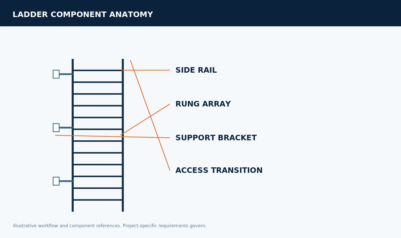
Component Detail Organization
Side rails, rungs, standoff clips, and part tags organized for shop manufacture and piece-by-piece assembly.
Optional 3D models, CNC files, detailed calculations and specialized fall-protection documentation are not included automatically. Confirm each deliverable in the project quotation.
Dimensional Standards & Clearances
Coordinating Rung Spacing, Side Rails and Required Clearances
The ladder geometry shown on a shop drawing must be traceable to approved project criteria. Important references include the intended rung arrangement, usable clear width, relationship to the support surface, headroom and climbing-side clearance, distance from the wall or other obstruction, and the appropriate top access transition. The specific requirements depend on the site and whether general industry, construction or other rules apply.
OSHA 29 CFR 1910.23 includes minimum and maximum rung centerline spacing and multiple fixed-ladder clearance provisions. Those requirements must be evaluated for the actual project, not copied as a generic detail into every sheet. For example, an equipment access ladder with adjacent piping may need a different obstruction review than an open exterior building wall. An alteration to the intended landing height may also affect rung count, rail extension and upper attachment conditions.
The detailing workflow should identify missing finished elevations, conflicting opening sizes, unclear structural supports and any field dimensions that cannot be established from the available documents. A fabricated dimension should not be presented as confirmed when the source information has not been approved.
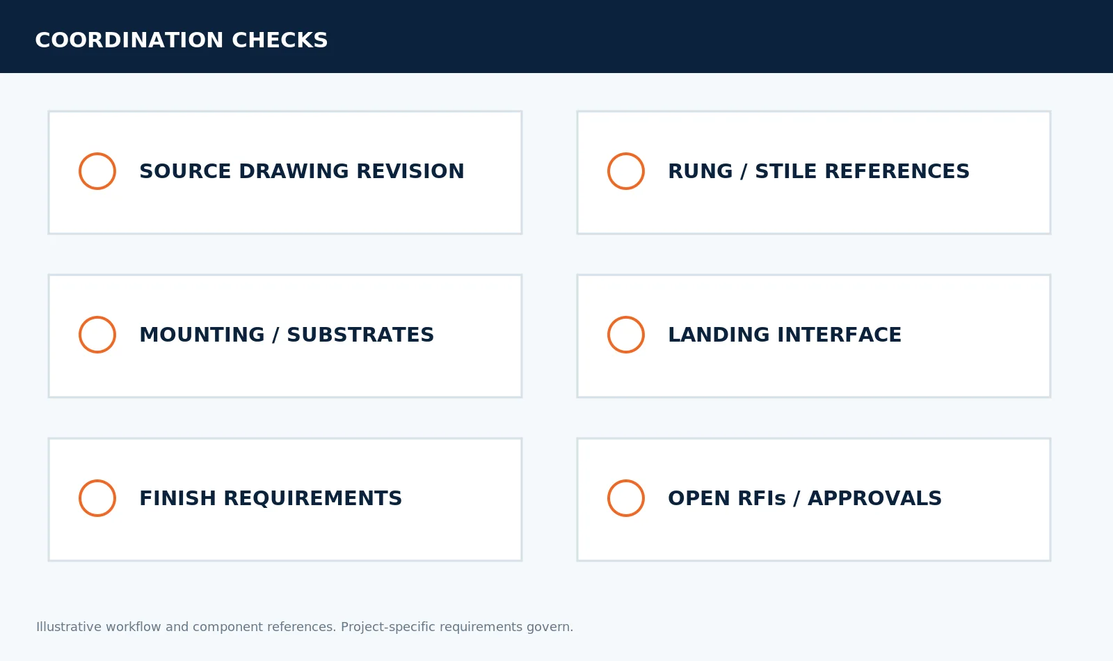
Technical Drawing Coordination Checklist
Substrate & Attachment Interfaces
Ladder Mounting Bracket and Connection Detailing
Bracket detailing is often the interface between a straightforward ladder assembly and a difficult site condition. The ladder may connect to a concrete wall, structural steel, masonry, equipment framing or a project-specific support. Each interface has different design inputs, tolerances and installation access requirements.
Shop drawings may identify plate geometry, bracket orientation, shop weld references, authorized field bolt locations, fastener or anchor schedules and the location of each attachment group. The bracket design and anchors must come from the responsible design professional or an approved delegated engineer where required. Do not select anchor embedment, edge distance, weld size or load rating based on appearance alone.
Review whether the supporting material and anchor layout match the issued drawings. Confirm any conflicts involving insulation, cladding, waterproofing, wall openings, reinforcement, embedded items or equipment. Where the contract drawings omit connection information, flag the omission before preparing fabrication-level details.
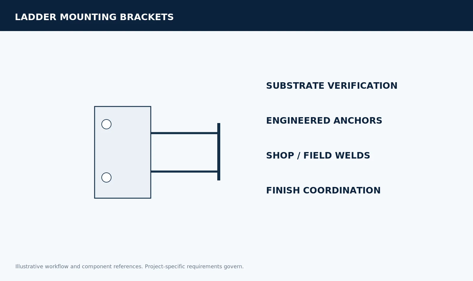
Wall Standoff Bracket Assembly
Detailing plate thickness, slotted holes, weld callouts, and minimum standoff clearances.
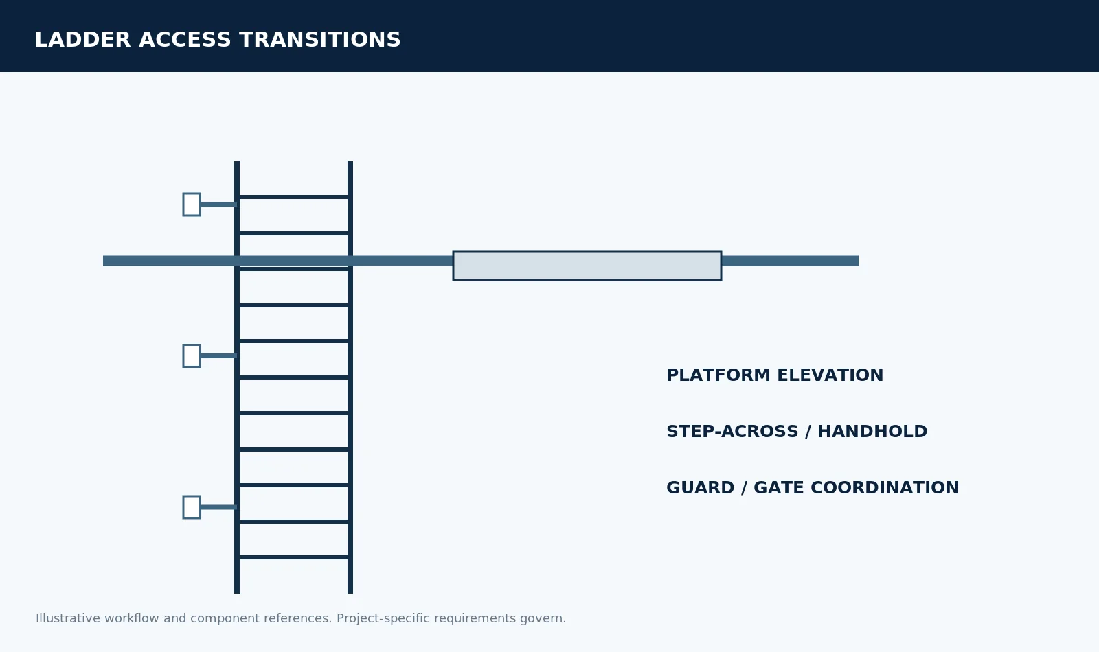
Roof Parapet & Hatch Transition
Coordinating walk-through extensions, self-closing safety gates, and roof curb clearances.
Egress & Walk-Through Interfaces
Roof and Platform Access Details That Need Extra Coordination
The transfer from a ladder to a landing is one of the most important geometric interfaces in a fixed ladder package. A ladder's position may appear correct in an elevation while the upper exit conflicts with a roof curb, hatch, guard post, platform opening or adjacent wall finish. Drawing coordination should therefore consider plan position and section height together.
When the scope includes roof or platform access, document the relevant landing elevation, step-across relationship, specified handholds or rail extensions, guard opening and access gate conditions. Identify which items form part of the ladder package and which belong to the structural steel, roof, architectural metal or safety-system contractor.
In existing buildings or plants, verify field conditions when required rather than assuming dimensions printed on older documents remain accurate. If the final geometry cannot be resolved from available information, issue a clear clarification request.
Regulatory Boundaries & OSHA 1910.28
How Ladder Safety Systems Affect Drawing Coordination
Not every ladder shown with a cage meets the fall-protection rules applicable to the installation. OSHA 29 CFR 1910.28 addresses fall protection for fixed ladders extending more than 24 feet above a lower level. Under the general-industry provisions, new affected fixed ladders installed on or after November 19, 2018 need a personal fall arrest system or ladder safety system rather than relying on a cage alone. Existing installations, replacement work and phased compliance involve additional provisions, including the November 18, 2036 transition deadline.
A cage may be present for historical, site-specific or supplementary reasons, but it must not be labeled as a universal code-compliant substitute for a required ladder safety system. The correct determination depends on the actual site, exposure, installation date and governing rules. Construction activity is addressed under separate requirements such as OSHA 1926.1053.
For drawing coordination, identify whether a ladder safety system is within the contracted scope and who supplies its design. A rail, cable or other fall-arrest interface can affect brackets, available space, rung geometry, top transitions and installation sequence. Specialist equipment, engineered anchorages, rescue requirements and final certification should remain with appropriately qualified providers and the responsible project parties.
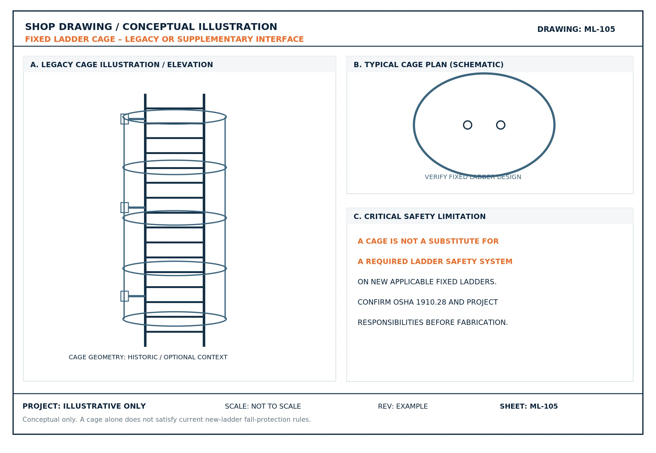
Legacy Ladder Cage Reference
Cautionary ReferenceCages alone do not meet fall-protection rules for new fixed ladders over 24 ft under OSHA 1910.28. Documented for retrofits and legacy contracts only.
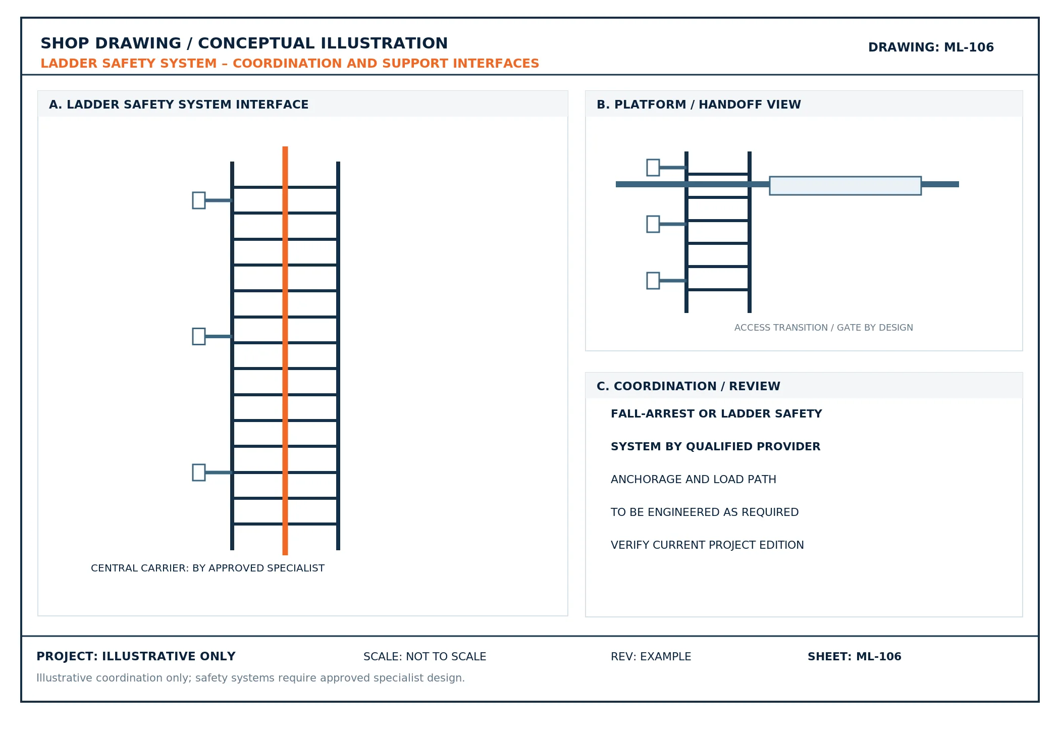
Ladder Safety System Interface
Modern CoordinationDetailing carrier rail and cable sleeve mounting brackets and climber dismount clearances without assuming specialist engineering liabilities.
Shop Component Organization
Side-Rail, Rung and Bracket Fabrication Documentation
After source documents are confirmed, the ladder package can be organized into individual fabricated pieces and assemblies. This may include side rails, rungs, intermediate supports, bracket plates, top return elements and other assigned components. Each item should have a consistent mark or identifier across the arrangement, component drawings and material schedule.
The shop should be able to trace a detail from the arrangement view to the applicable fabrication sheet and any authorized finish requirements. Material grade, member section, welding procedure, protective finish and field connection requirements must follow the project specification rather than an assumed standard detail. Exposed metalwork may require particular attention to galvanizing, corrosion protection or compatibility with adjacent building finishes.
Clear part organization also helps control the effects of revisions. A changed bracket location may influence a side-rail sheet, connection detail, hole pattern and assembly schedule. The revised package should identify exactly which sheets were superseded and which clarifications remain open.
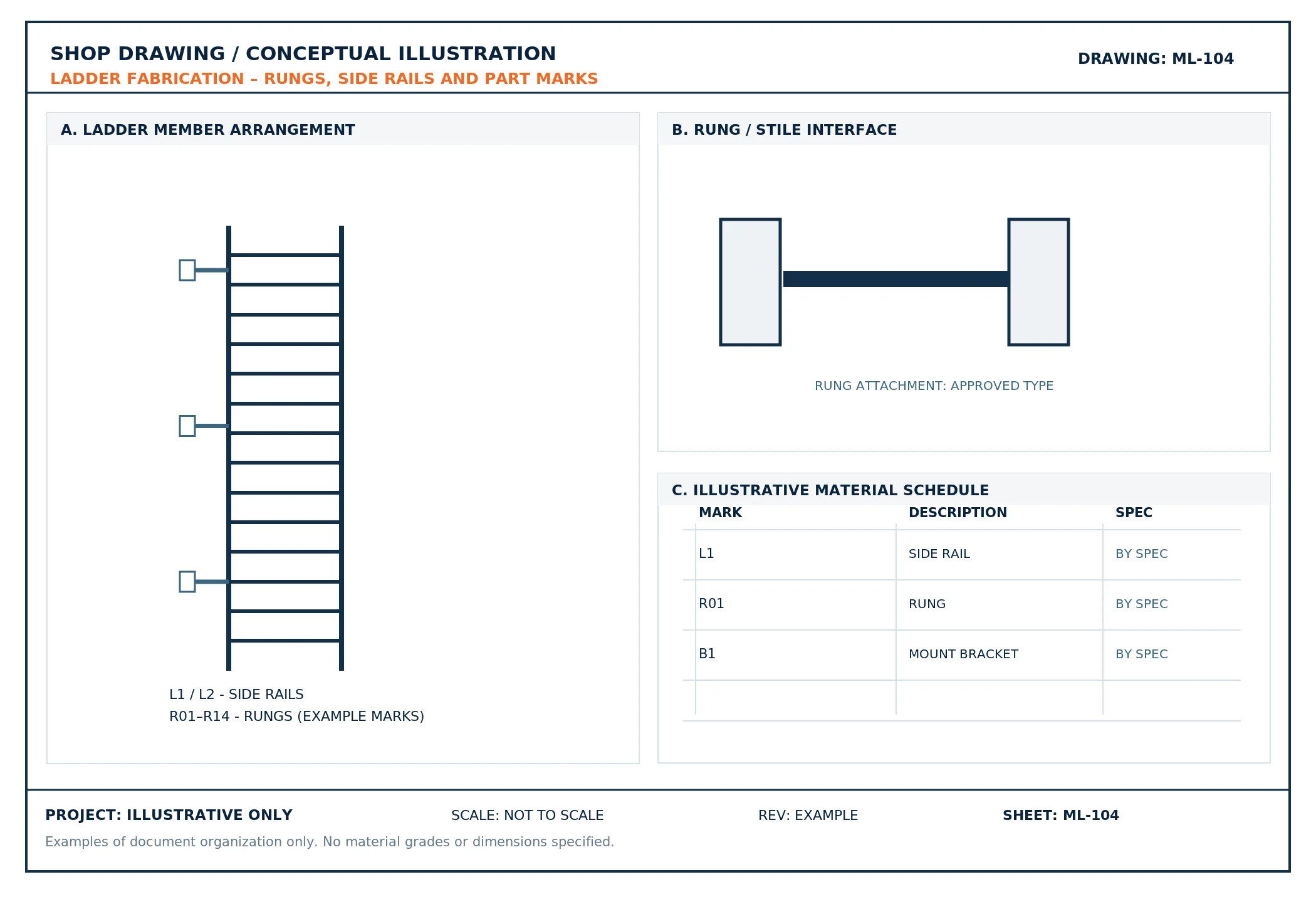
Piece Marks & Cut Schedules
Punch layout, non-slip rung details, weld symbols, and bill of materials.
Quality Assurance & Risk Mitigation
Typical Conflicts to Catch Before Ladder Fabrication
The purpose of drawing review is to identify and communicate mismatches, not to replace project engineering, field inspection or safety approvals.
| Issue | Potential Consequence | Drawing-Stage Action |
|---|---|---|
| Different roof levels between architectural and structural plans | Incorrect top-of-ladder transition | Verify approved elevation references |
| Unclear mounting substrate or missing anchor design | Unresolved bracket connection | Request engineer-approved connection information |
| Plant equipment or piping obstructs climbing clearance | Interference with intended ladder route | Coordinate with current plant layout and field conditions |
| Guard opening, gate or hatch conflicts with ladder exit | Awkward or blocked transfer at the landing | Reconcile plan and section interfaces |
| A cage is shown as the sole fall-protection solution on a new affected ladder | Potential noncompliance with applicable OSHA provisions | Refer the requirement to responsible safety/design parties |
| Rung spacing or ladder length changed without updating related sheets | Inconsistent fabrication information | Revise all dependent views and schedules |
| Surface finish or corrosion system omitted | Unclear fabrication and coating scope | Confirm the specified finish before release |
| Fabricator uses superseded drawing revisions | Incorrect component manufacture | Maintain a clear current-issue register |
Cross-Discipline Coordination
Reconciling architectural roof levels, structural steel framing, and MEP piping clearances before cutting steel.
Deliverable Previews & Technical Samples
Illustrative Fixed Ladder and Access Detail Sheets
Our sample sheets show how a ladder package can organize arrangements, member references, supports and interfaces. The examples are conceptual and do not represent completed client projects or engineer-approved construction details. The actual content of a fabrication release depends on the approved contract documents and project-specific requirements.
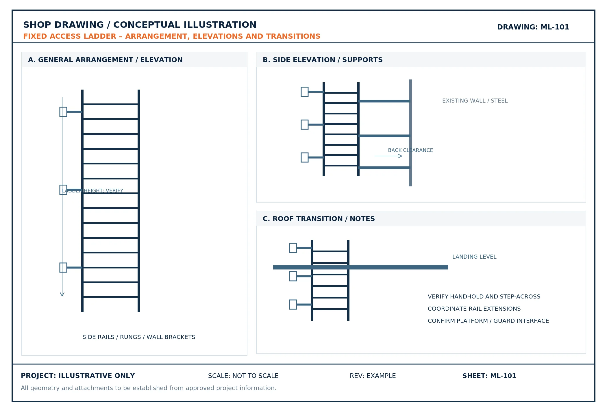
Fixed Ladder General Arrangement
Illustrative front and side elevations showing ladder rails, rungs, wall supports and upper landing coordination.
- Overall vertical climbing height and top-of-landing elevation coordinates
- Side-rail profiles, ladder clear width and uniform rung pitch references
- Wall-bracket standoff distances and vertical support spacing datums
- Datum references coordinating ladder location with building grid lines
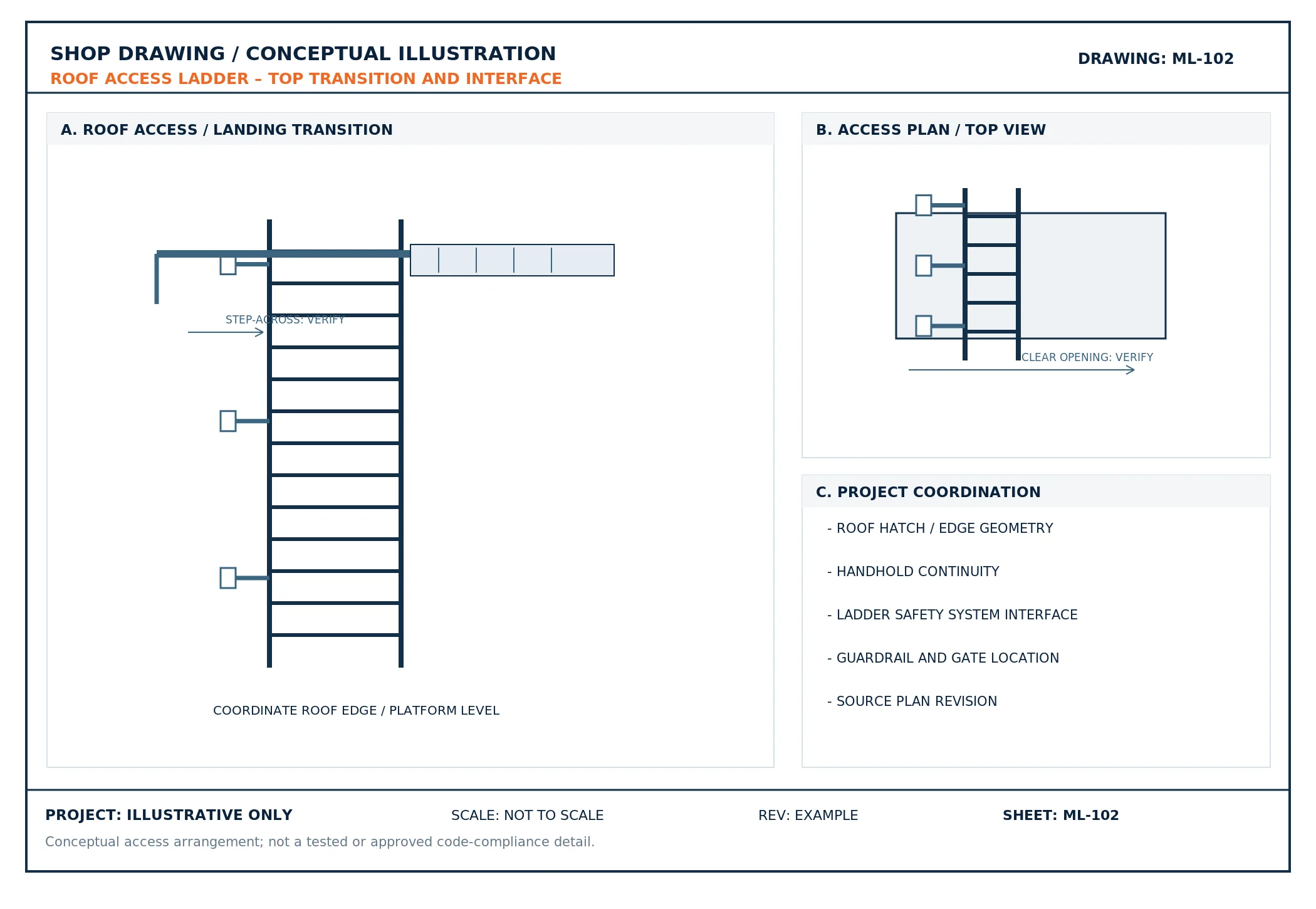
Roof Access and Landing Transition
Conceptual roof access drawing showing an upper landing interface, handhold considerations and items requiring field verification.
- Walk-through side-rail extension geometry with 42-inch grab-bar height
- Step-across clearance between ladder centerline and roof landing threshold
- Self-closing safety gate and surrounding perimeter guardrail attachment references
- Items flagged explicitly for field verification against actual roof curb heights
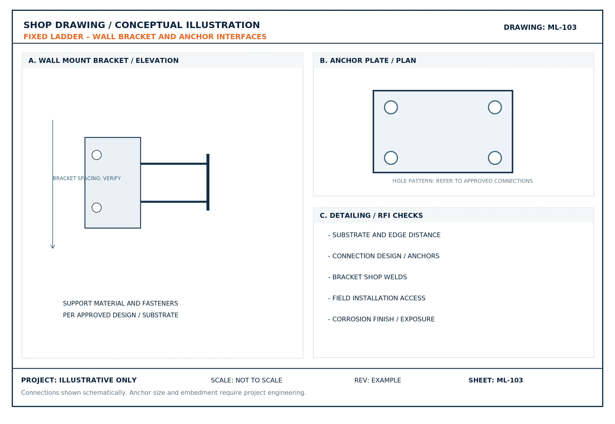
Wall Bracket and Anchor Detail
Bracket arrangement and anchor plate views identifying the interface that needs approved structural connection information.
- Standoff angle/plate geometry maintaining minimum 7-inch wall clearance
- Shop-welded bracket-to-rail joints with designated weld sizes and symbols
- Hole patterns, slotted adjustment tolerances, and field fastener callouts
- Interface notes referencing engineer-approved concrete, steel, or CMU substrate backing
Ladder Rungs, Side Rails and Part Marks
Example fabrication sheet organization for rung and side-rail assemblies, component marks and a material schedule.
- Side-rail bar and channel section dimensions with hole punch layout
- Serrated, diamond-traction, or knurled round rung fabrication callouts
- Piece-mark callouts matching the master bill of materials and cutting lists
- Galvanizing vent holes, finish specifications, and corrosion protection callouts
Legacy Ladder Cage Reference
Conceptual ladder cage drawing with an explicit warning that cages alone do not satisfy the required safety systems for new affected fixed ladders.
- Hoop bar curvature, vertical strap spacing, and cage flare bottom entrance details
- Stipulation that cages alone do not meet fall-arrest rules for new ladders > 24 ft under OSHA 1910.28
- Documentation for existing facility retrofits, maintenance repairs, and legacy contracts
- Clear regulatory notation referencing the November 18, 2036 phase-out deadline
Ladder Safety System Interface
Illustrative coordination views for a separately designed ladder safety system, ladder rails and platform transition.
- Mounting bracket clearances for center-mounted cable sleeve or rigid-rail carriers
- Top-of-ladder safety system mast/extension bracket for safe climber dismount
- Bottom tensioning bracket anchor coordinates and unobstructed climbing clearance
- Clear trade responsibility delineation separating detailing from specialist certification
Disclaimer: Illustrative drawing samples only. Not approved for fabrication, installation, engineering design, fall-protection certification or code compliance verification.
Quotation Checklist
What to Send for a Metal Ladder Shop Drawing Quotation
A clear quote begins with the intended fixed-ladder assemblies and the current project documents. Mark each ladder's location and quantity, especially when a site contains repeated tank, roof and equipment access ladders. Identify work assigned to the ladder detailer and components handled by other trades.
If source information is incomplete, identify missing items up front. A reliable scope should not assume unknown dimensions, engineered anchors or safety-system components.
Submit Your Ladder DrawingsWorkflow & Quality Control
From Ladder Scope Review to Organized Drawing Deliverables
The design team, responsible fabricator, installation contractor and safety-system specialist maintain their respective contractual responsibilities.
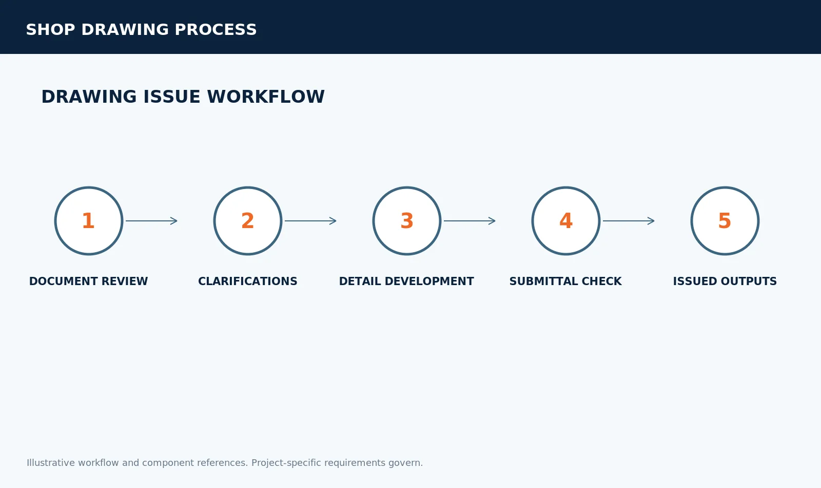
Review the Assigned Ladder Scope
Review project drawings, access locations, specifications, quantities and requested outputs. Identify which structural, roof or equipment components belong to separate packages.
Flag Coordination Questions
Record unclear levels, insufficient support information, absent connection design, access conflicts, field verification requirements and safety-system ownership questions.
Prepare the Detailed Drawings
Develop the agreed general arrangement, fabrication views, assembly references, mounting brackets and schedules using the current approved information.
Check Cross-References and Revisions
Reconcile component marks, ladder geometry, attachment locations, drawing notes and the latest authorized documents before submission.
Issue the Agreed Deliverables
Provide the specified drawing package for the contractual review or fabrication stage. Incorporate authorized revision comments under the agreed service scope.
Deliverable Specifications
PDF, CAD and Model-Based Ladder Deliverables
PDF drawing sets are commonly used for submittal review and controlled issue. Depending on scope and the actual software workflow, the package may include DWG or DXF files, assembly models, parts schedules or specific fabrication exports. These digital outputs must be defined in the quotation rather than presumed available for every job.
Vector PDF Packages
Full-scale vector drawing sets formatted for standard 11x17 or 24x36 sheets with complete title blocks.
DWG / DXF CAD Files
Layered 2D CAD files compatible with AutoCAD for easy contractor integration and shop coordination.
3D Model References
Coordinated 3D assemblies referencing structural backing models where explicitly included in scope.
Cut Schedules & BOMs
Tabular cutting lists and bill of materials detailing member sections, lengths, and part marks.
Where a ladder is coordinated in a larger structural model, provide a clear reference between the model and issued drawings. Do not treat an illustrative 3D picture as a reviewed fabrication model. Native authoring files, CNC-ready exports, bolt schedules, engineered calculations and fall-protection product details are optional only when explicitly included and properly supported.
Governing Codes & Clear Boundaries
Fixed Ladder Standards and Project-Specific Requirements
Metal ladder drawings should reflect the contract and the rules applicable to the actual installation. In many US industrial workplaces, OSHA 29 CFR 1910.23 establishes fixed-ladder construction and clearance requirements, while 1910.28 establishes relevant fall-protection duties. Construction-phase ladder rules are addressed under OSHA 1926.1053. Industry references such as ANSI/ALI A14.3 may also be specified, but should not be imposed universally or treated as a replacement for regulatory requirements.
Fixed ladders differ from portable ladders and inclined steel stairs. Their geometry, access conditions, fall exposure and attachment arrangements require specific review. Material and weld standards depend on the project design documents and fabricated materials; referencing a standard does not establish that the finished installation has been independently certified.
Our standard detailing service organizes approved project information into shop drawings and flags inconsistencies. Structural analysis, connection engineering, fall-arrest design, rescue plans, professional engineering seals, jobsite inspections and certification are separate responsibilities unless clearly arranged with qualified providers.
Industry Partners
Fabrication Documentation for US Construction Teams
These are service applications tailored to the specific submittal, fabrication, and erection challenges encountered by each team.
Miscellaneous-Metal Fabricators
Need component sheets, assembly references, approved attachments, finish notes and accurate mark organization to prepare shop work.
General Contractors
Need a documented submittal package and clear coordination questions where roof interfaces, structural supports or subcontractor boundaries are unresolved.
Industrial and Plant Contractors
Need maintenance access geometry aligned with equipment, structures, pipework and any required field information.
Roofing and Building Envelope Teams
May need to coordinate access ladder interfaces with curbs, hatch openings, flashing details, cladding and roof edges without assuming responsibility for ladder engineering.
Architectural and Structural Design Teams
Review submittal information according to the contract, confirm design intentions and answer missing-information requests.
Pricing & Project Timelines
What Determines a Metal Ladder Detailing Quotation?
The cost of a fixed ladder drawing package depends more on the number of unique assemblies, attachment complexity and completeness of design information than on a simple per-sheet assumption. A repeated wall ladder with a verified bracket detail differs from a tank or roof-access ladder requiring specialized transitions, multiple structural interfaces and coordination with a fall-protection provider.
Pricing and schedule considerations include ladder count, overall geometry, repeated versus unique component types, bracket and anchor detailing scope, field survey needs, specialist safety equipment interfaces, requested model outputs, expected review cycles, and the speed at which design questions are answered.
For broader project planning and preconstruction budgeting, teams often evaluate overall material and takeoff estimates alongside detailing requirements through professional construction estimating and quantity takeoff services. Share the current plans and a marked ladder schedule for a scope-specific quotation. Do not promise a universal delivery deadline, fixed price, code approval or unlimited revisions.
Scope Boundaries & Scope Comparisons
Fixed Ladder Detailing Is Not the Same as Steel Stair Detailing
A fixed ladder generally uses vertical or near-vertical climbing geometry with rungs and side rails, while a steel stair package includes an inclined walking path with flights, treads, risers, stringers and landings. Both may connect to steel platforms or building framing, but their fabrication views and applicable access rules differ.
A project needing an inclined industrial stair should be reviewed under the steel stair shop drawings scope rather than forcing the requirement into a fixed-ladder package. A project needing both a platform and ladder may require separate steel platform and catwalk drawings together with the ladder assembly and interface details.
Common Questions
Metal Ladder Shop Drawings — Frequently Asked Questions
Practical answers to questions regarding drawing scopes, code applicability, submittals, and fabrication coordination.
Need Metal Ladder Shop Drawings for Your Project?
Send your ladder locations, elevations, support details and project specifications for review. We'll assess the proposed drawing scope and provide a project-specific quotation for the required fabrication and coordination deliverables.