
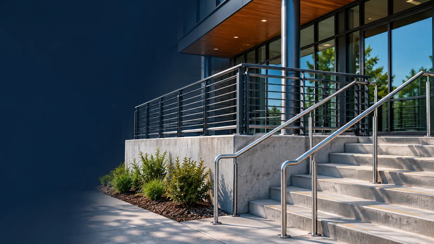
Guardrail & Handrail Drawings for Fabrication & Installation
Guardrails and handrails do different jobs, but both need precise coordination with stairs, ramps, balconies, landings, platforms and the surrounding structure. Our guardrail and handrail drawing service prepares project-specific layouts, elevations, attachment details and fabrication information for the agreed metalwork scope. US contractors and fabrication shops can submit their plans, system requirements and project schedule to request a detailed drawing proposal.
Design Intent & Functional Differences
Drawings That Define Protection, Graspability and Fabrication Interfaces
A guardrail or guard is generally intended to protect an open edge at a balcony, mezzanine, platform, stair or other elevated walking area, subject to the relevant code and location. A handrail provides a graspable support along a stair, ramp or walking surface. Some assemblies combine both functions, but their required geometry and performance criteria are not interchangeable.
Guardrail and handrail shop drawings translate the approved project requirements into coordinated fabrication and installation information. Typical documentation includes system plans, panel elevations, post positions, top-rail and infill details, bracket locations, attachment interfaces, materials, finishes and revised drawing references.
At a stair landing, for example, a guard panel may continue along an exposed edge while a separate graspable rail turns or extends to suit the stair design. A useful drawing package makes each system's location and connections clear rather than showing every metal rail as an identical assembly.
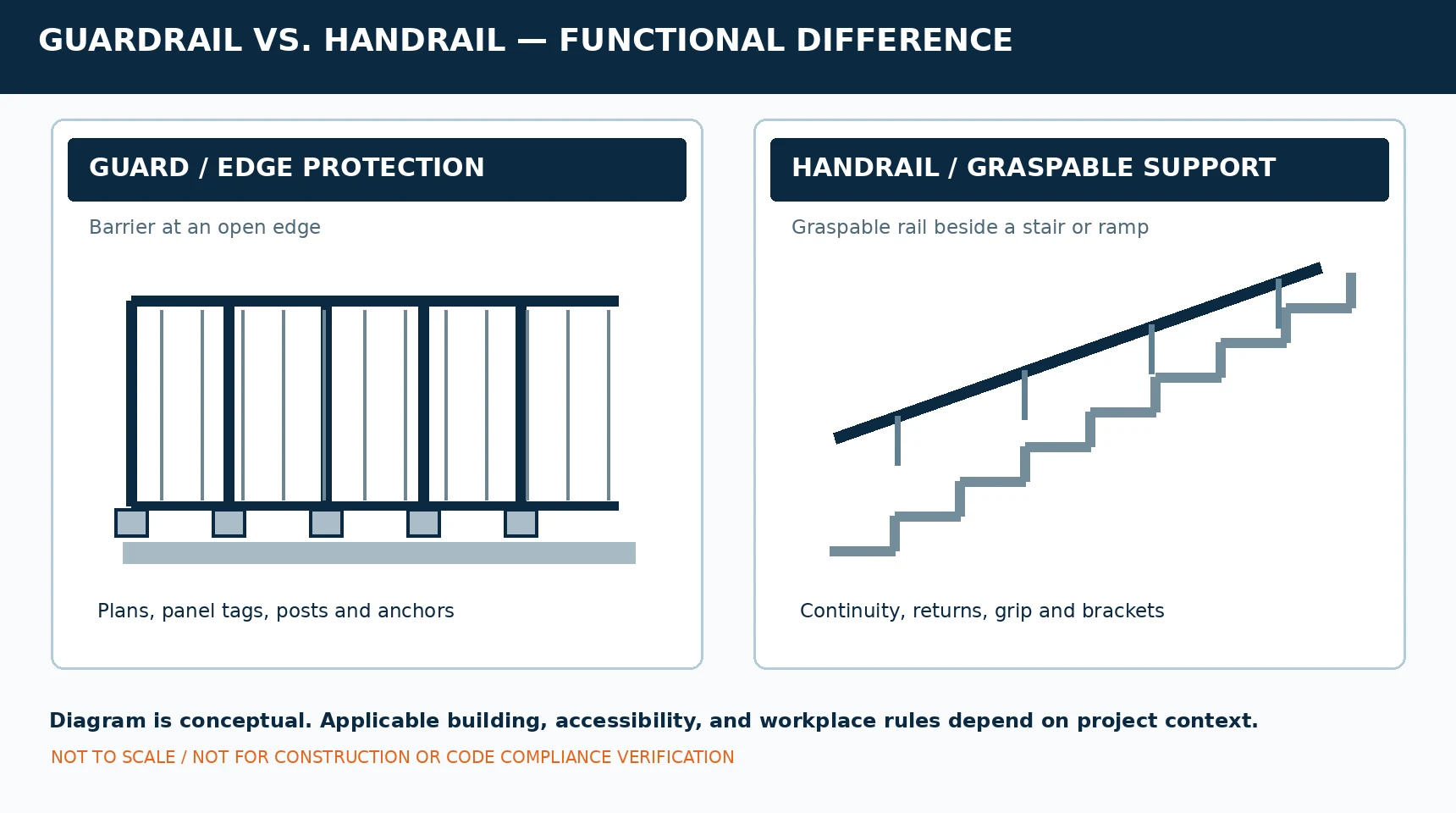
Guardrail vs. Handrail Functional Separation
Illustration showing distinct geometry between edge-protection guard assemblies and graspable handrail systems.
| Feature | Guardrail / guard | Handrail |
|---|---|---|
| Primary purpose | Edge protection where required | Graspable support for users |
| Typical locations | Balconies, mezzanines, platforms, open sides of stairs | Stairs, ramps, wall-adjacent travel paths |
| Drawing emphasis | Panels, posts, infill, openings, anchorage | Grip profile, continuity, returns, brackets, clearances |
| Engineering / code | Approved guard loads and local code criteria | Applicable handrail and accessibility rules |
| Overlap | A guard assembly may include a handrail | May be separate from the guard |
System Applications
Drawing Support for Common Guard and Handrail Applications
Our scope is defined by the actual project documents. The following are common assemblies for which contractors and specialty-metal fabricators request drawings. The material, approved design, attachments and necessary reviews differ by application.
Stair & Landing Guards
Guard panels at open sides of flights and landings, with sloping elevations, corner transitions, post locations and interfaces with the stair construction.
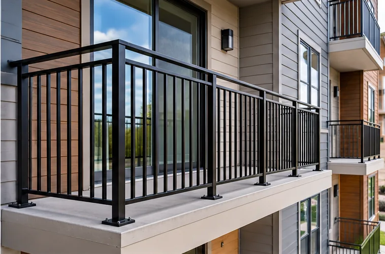
Balcony Guards
Guardrail elevations, panel marks, corner conditions, slab-edge attachments and materials for exposed or enclosed building balconies.
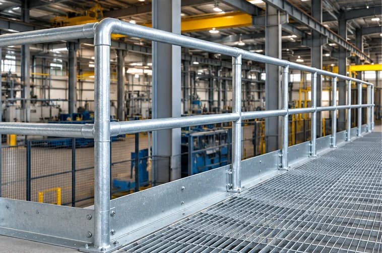
Industrial Platform Guards
Perimeter guards on equipment platforms and maintenance walkways, with midrails, access openings, gates or toe plates where specified.
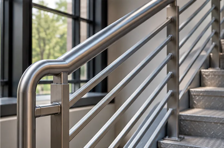
Stair Handrail Interfaces
Graspable rail profiles, returns, handrail continuity, bracket locations and transitions between flights, landings and adjacent guards.
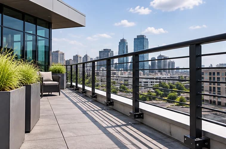
Rooftop & Terrace Guards
Parapet and terrace perimeter conditions, attachment coordination, changes in elevation and the relationship between guards and roof assemblies.
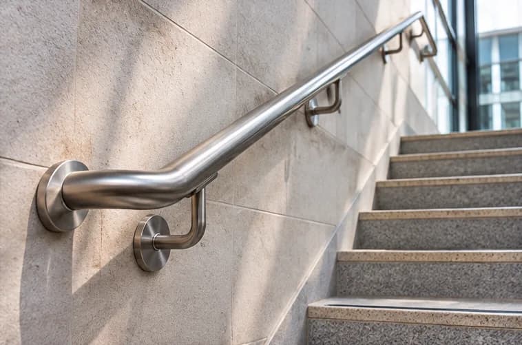
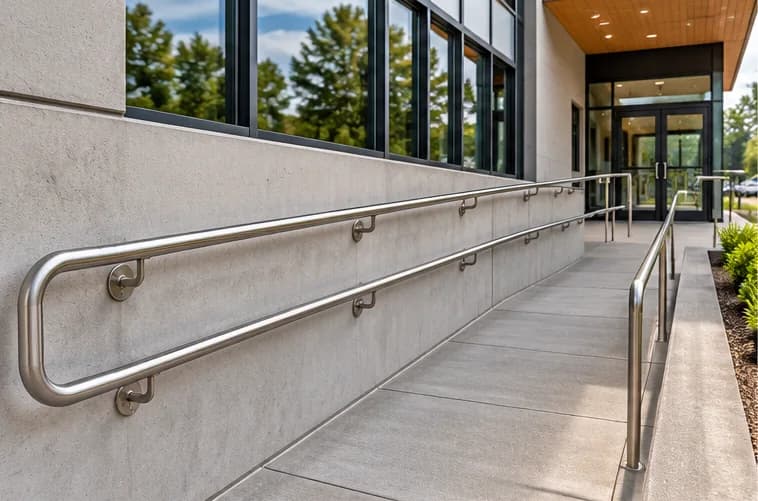
Wall-Mounted Handrails
Wall brackets, rail offsets, returns, termination points, mounting substrates and finish coordination along stairs or ramps.
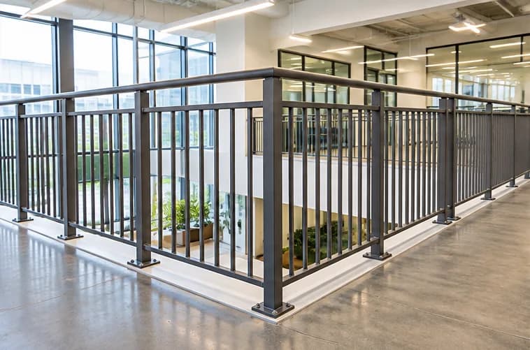
Mezzanine & Interior Guards
Straight and corner guards around floor openings and upper levels, including infill, post/base details and coordination with finishes.
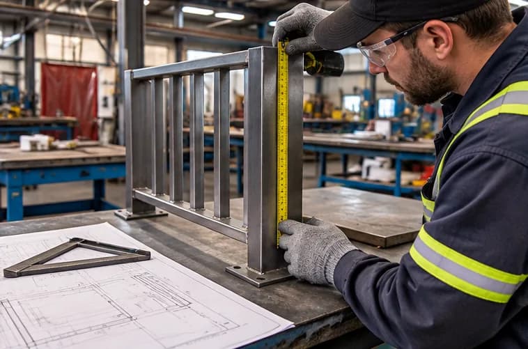
Custom Fabricated Rail Systems
Project-specific welded or bolted components requiring component marks, assembly views, attachment schedules and shop/field coordination.
Coordinating complete stairs or specialized primary steel? Explore our dedicated Steel Railing Shop Drawings Page, Steel Stair Shop Drawings Page, and Miscellaneous Metals Detailing Services.
Submittal Deliverables
Guardrail and Handrail Shop Drawing Deliverables
A useful submittal set allows the fabricator and project reviewers to locate the correct details quickly. The precise deliverables depend on the contract, system manufacturer, approved design information and the negotiated drawing scope.
| Deliverable | Information typically documented | Value to the project |
|---|---|---|
| Layout plans | Guard and rail positions, runs, reference levels, openings and changes in direction | Defines where each system belongs |
| Railing elevations | Panel height, slope, infill pattern, post spacing, rail transitions | Describes the intended visible assembly |
| Typical sections | Top rail, midrail, infill, brackets and support sections | Clarifies geometry and interfaces |
| Post and panel marks | Segment identifiers, quantities, assembly references | Connects drawings and shop lists |
| Anchorage/connection references | Approved base plates, brackets, steel/concrete interfaces, bolts and weld notes | Communicates attachment requirements |
| Handrail continuity details | Returns, extensions, corner transitions, wall offsets and gripping profiles | Supports review of handrail-specific criteria |
| Material and finish schedules | Specified materials, sections, coatings and component references | Coordinates the agreed fabrication scope |
| Revision and submittal records | Sheet issue information, updated details and outstanding comments | Reduces superseded-information conflicts |
Note: Do not promise fabrication engineering, anchor load design, stamped calculations, laser-cut files, BIM or native CAD formats as standard unless specifically contracted.
Panel Coordination
Coordinating Guard Panels Before Fabrication
Guardrail elevations must reconcile the approved overall design with actual building edges, levels, supports and architectural finishes. A long straight railing may use repeatable panels, but stair transitions, corner returns and changes in substrate often require separate details.
Plans identify the intended location of each run and its relationship to edges, openings and walls. Elevations help document top-rail profiles, visible infill arrangements, panel lengths, post marks and slope changes. Sections locate the metalwork relative to the support surface. If field measurements are required, they should be clearly identified instead of treated as already confirmed dimensions.
The documentation should distinguish approved design information from details still awaiting an RFI or project-team decision. This is especially relevant where a guard meets a stair railing, wall, glass partition, parapet or metal screen.
Key Detailing Checklist:
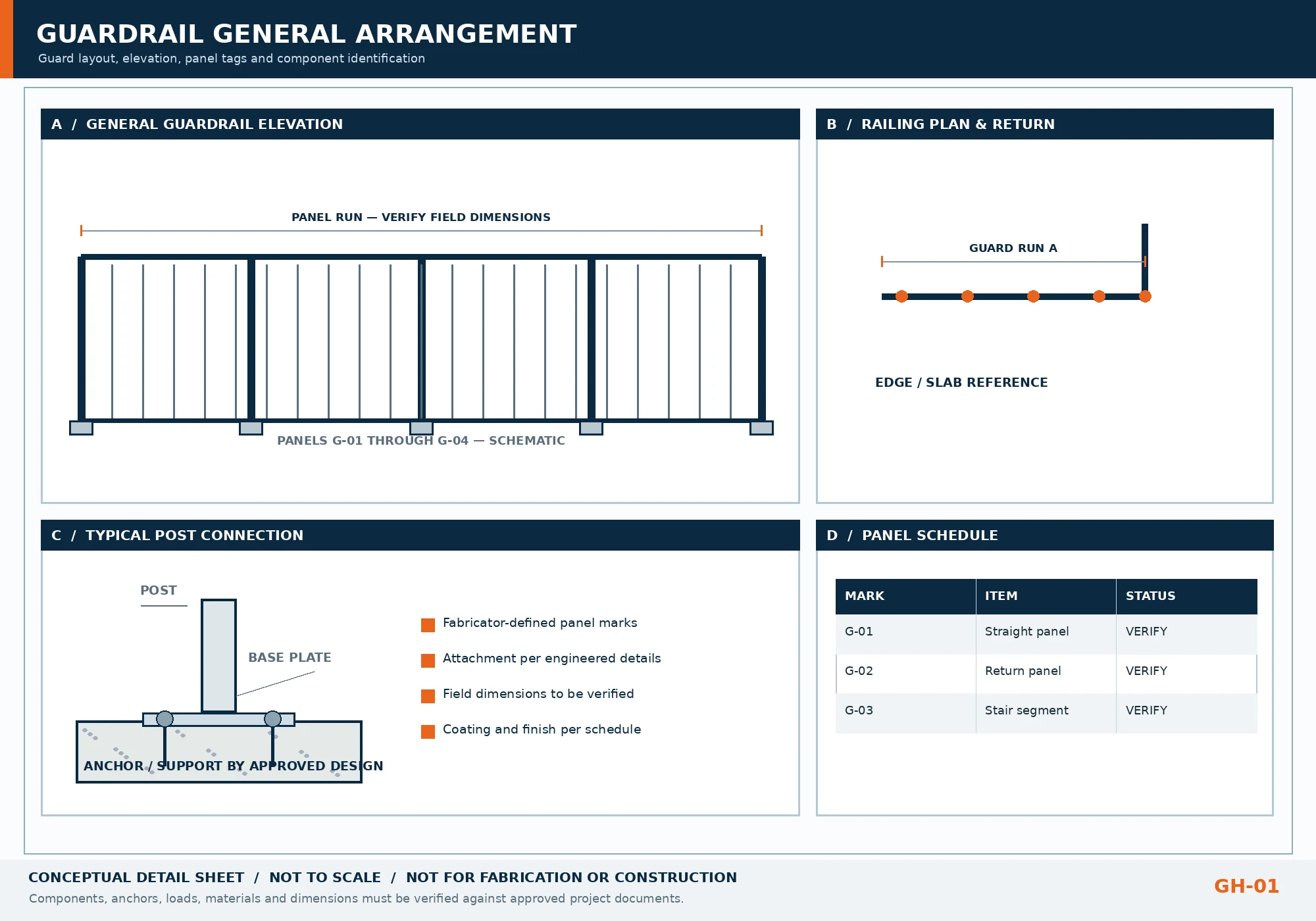
Sample Sheet G-101
Guardrail General Arrangement
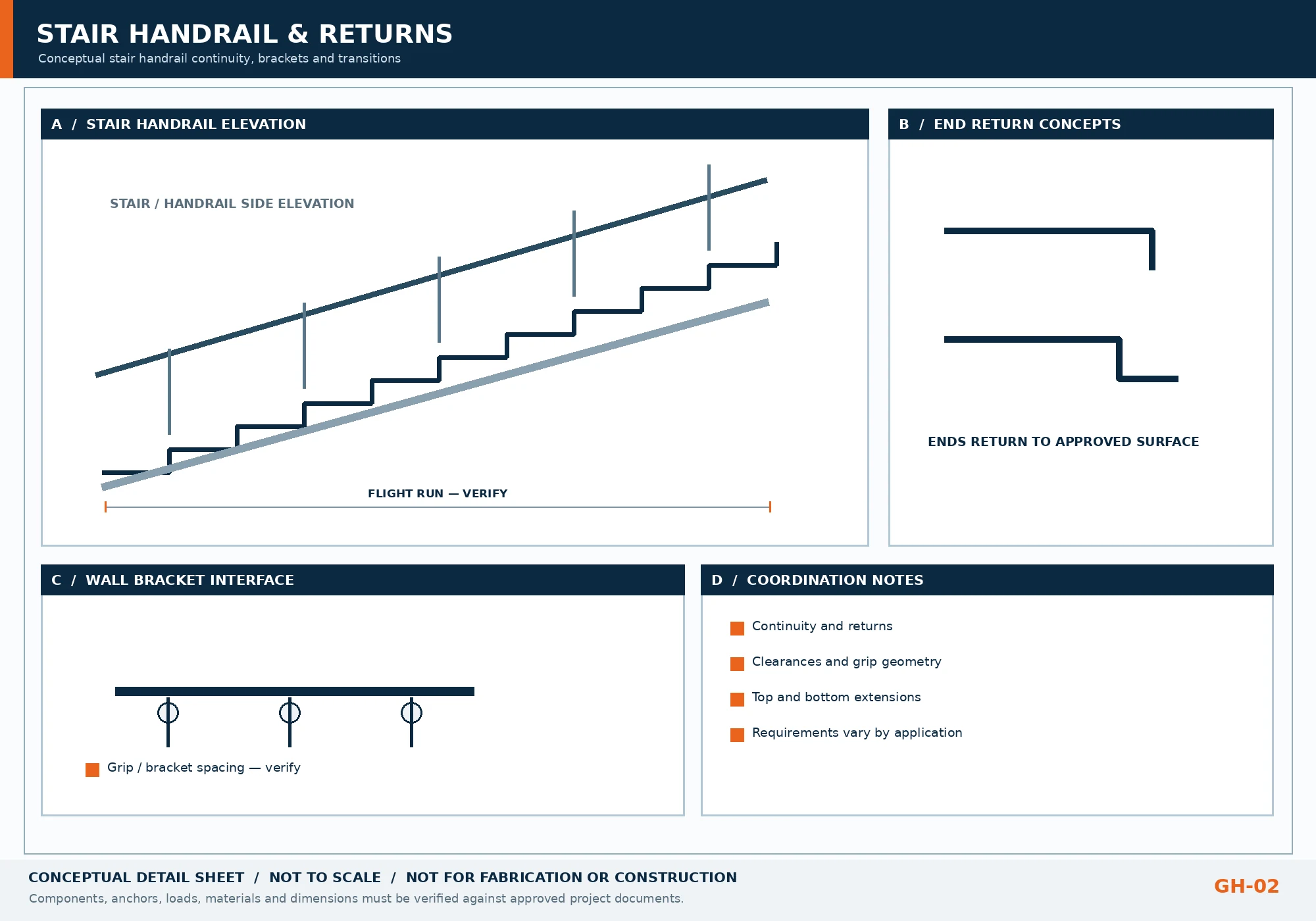
Sample Sheet G-201
Stair Handrail & Returns
Handrail Geometry
Stair Handrail Details Beyond a Basic Elevation
A stair handrail package needs a clear graspable profile, continuous routes where required, bracket or post attachments, appropriate clearances and the intended end conditions. A top guard member is not automatically a suitable handrail. The project design must identify whether the handrail is separate, mounted to the guard, or supplied as another arrangement.
At changes in flight direction, the drawing set should coordinate inner handrail continuity, offsets and return geometry. At the start and end of a flight, the approved detail should communicate extensions and terminations where applicable. Wall finishes and nearby doors can affect bracket position and available clearances.
Exact design criteria must reflect the governing project standards. For example, the US Access Board's 2010 ADA Standards Section 505 addresses required handrails on covered accessible routes, including continuity, height, gripping surfaces and extensions. Those rules are not a blanket substitute for other locally adopted building codes or workplace regulations.
Useful Drafting Checks:
Top-of-grip reference, mounting/clearance, return direction, inside-turn continuity, connections to guards, and relationship to actual stair geometry.
Accessibility & Substrates
Ramp Handrail Drawings With Clear Bracket and Return Information
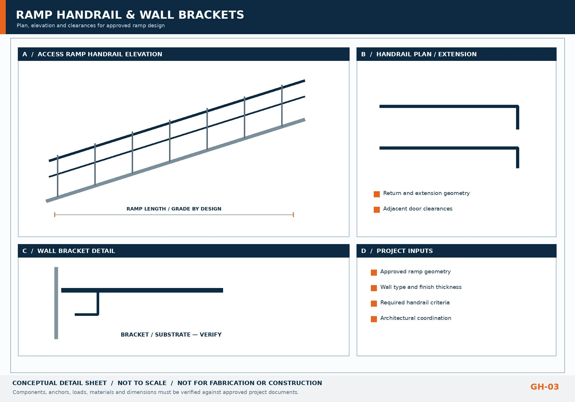
Ramp handrail detailing needs coordination with slope changes, landings, wall finishes and the specified accessibility requirements. The handrail's slope and height reference should follow the project-approved ramp arrangement. Sections and details may show wall stand-off brackets, post supports, changes in direction, rail transitions and the intended termination geometry.
A wall-mounted system also needs reliable information about the mounting substrate. A bracket connecting to structural concrete is different from a bracket at stud framing or a finished wall with concealed backing. The location and design of the required support must be confirmed by the appropriate project party before an anchorage detail is finalized.
In renovation work, measured wall and ramp conditions matter. Document discrepancies and coordinate with the designer instead of silently adjusting a compliant design assumption.
Key Drafting Inputs:
Ramp plan and elevations, wall sections, approved handrail profile, bracket details, finish thicknesses and any survey data.
Substrate Mounting & Wall Backing
Coordination of bracket spacing and wall attachment points.
Ramp Handrail & Wall Brackets Detail Sheet
Conceptual ramp rail elevation, extensions, bracket details and wall mounting coordination sheet. Click to inspect high-resolution sheet.
Sample Sheet G-401
Guard Post & Anchorage Details
Structural Interfaces
Connection Details Are a Critical Part of Guardrail Shop Drawings
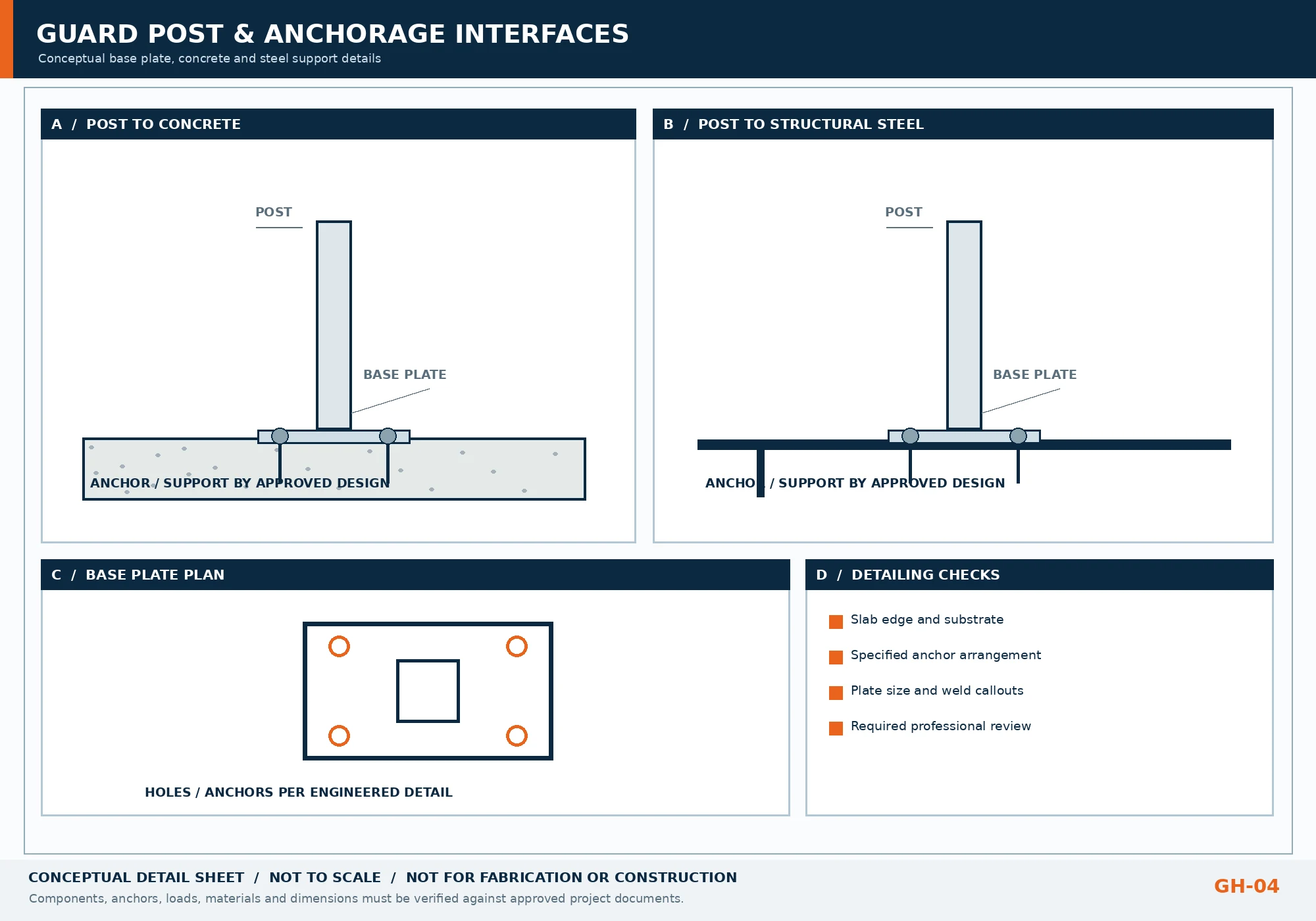
The attachment of a guard to its supporting structure often controls whether the fabricated rail fits the completed project. Typical interface conditions include concrete slabs, steel beams, embedded plates, wall faces, parapets and architectural finishes. Each can affect post position, base-plate arrangement, edge clearance and the accessible space for tools or fasteners.
Shop drawings should depict the approved post and connection geometry and identify any open design information. They should not independently specify unverified anchor embedment, plate dimensions, loads or weld sizing. Where engineered connections are required, the responsible qualified professional supplies or approves the design information according to contract arrangements.
Connection coordination should identify available slab thickness, edges, any waterproofing or covering, support member location, finish build-up and whether installation occurs before or after adjacent trade work. These details help avoid late changes to fabricated components.
Attachment Review List:
Building Perimeter Conditions
Guard Drawings at Exposed Building Edges
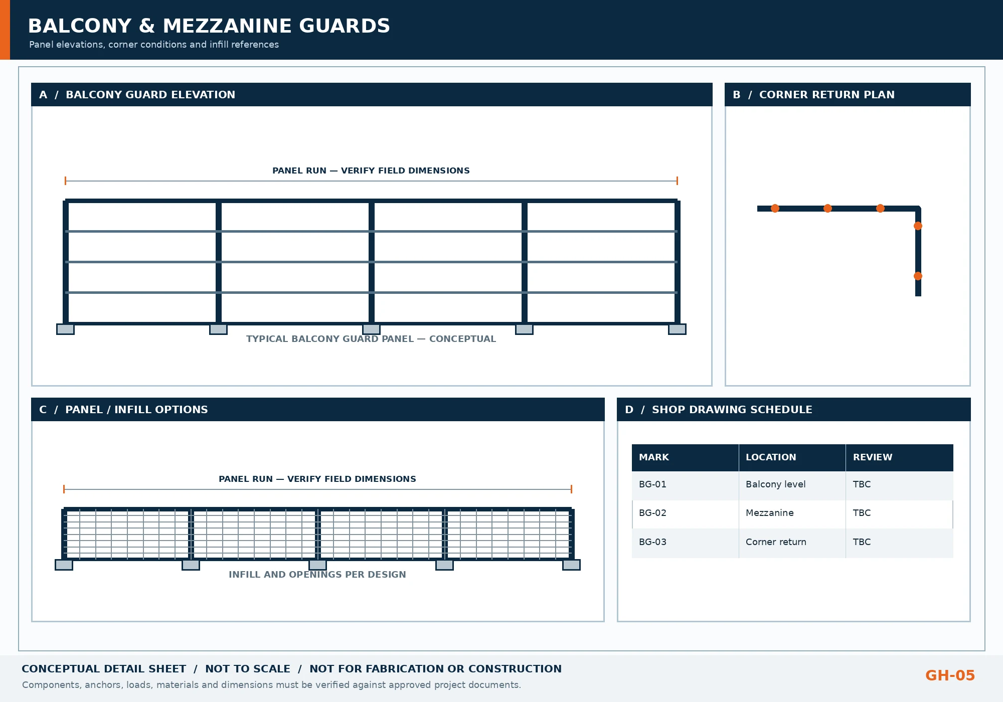
Balcony and mezzanine guards often have long runs interrupted by corners, façade walls, posts, doors, and changes in slab elevation. An accurate layout should distinguish straight panels, corner returns and transitions to adjacent metalwork. If railings are shipped as prefabricated segments, segment marks and field splice details must match the fabrication plan.
Exterior locations add finish and interface coordination. Roofing or waterproofing requirements, façade tolerances and drainage details come from the project documents. Guard drawings should communicate the agreed metalwork boundaries without implying responsibility for the entire building envelope.
For occupied roofs, mezzanines and other elevated areas, the requirement for a guard and its geometry depend on the building code, use and site-specific conditions. Do not assume all edges follow one standard detail.
Rooftop & Terrace Guard Assembly
Parapet conditions, waterproofing interfaces, and elevation changes.
Balcony & Mezzanine Guard Detailing Sheet
Typical guard elevations, corner return conditions, slab-edge attachments and panel schedule. Click to inspect high-resolution sheet.
Industrial Platform Railing & Toe Board
Platform edges, intermediate rails, and equipment access gates.
Workplace Safety Standards
Industrial Platform Guardrail Details and Access Interfaces
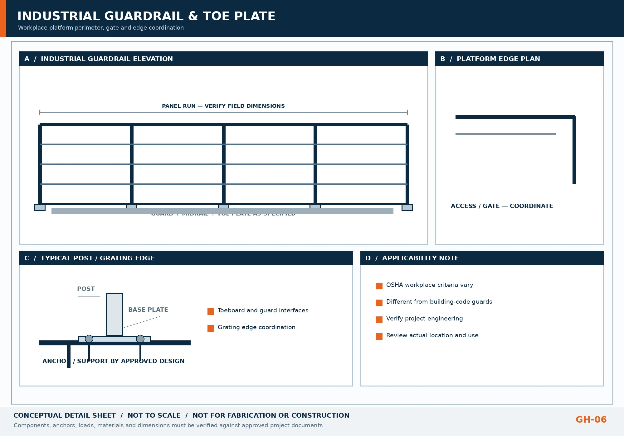
A guardrail used on a workplace platform or industrial walking-working surface may be subject to OSHA requirements rather than the same criteria applied to a commercial building balcony guard. In the applicable workplace context, drawings may address top rails, intermediate members, toe plates where specified, platform edges, gate openings and surrounding equipment.
Coordinate the guard geometry with grating, equipment maintenance access, stair connections and the supplied engineered support details. Any access gate should be documented according to the project requirements. Where a platform also serves as part of a building's occupied egress route, the governing requirements must be confirmed by the project designer.
OSHA 29 CFR 1910.29 contains specific criteria for covered general-industry guardrail and stair-rail systems. The responsible project team must establish when those provisions apply; do not copy a workplace guard detail onto a public stair or balcony without design review.
Industrial Guardrail & Platform Detail Sheet
Platform guard configuration, access gate interface, intermediate midrails, and toe-plate coordination. Click to inspect high-resolution sheet.
Code & Regulatory Context
Applicable Guardrail and Handrail Requirements Are Project-Specific
Guardrails and handrails are subject to different requirements depending on intended use, occupancy, building location and jurisdiction. A handrail helps people use stairs or ramps; a guard protects a walking surface edge. Their dimensions, performance criteria and attachment requirements need to come from the correct applicable sources.
For many permanent building applications, the locally adopted International Building Code (IBC) is relevant. IBC Section 1014 addresses handrails, while Section 1015 addresses guards. Where applicable, the 2010 ADA Standards Section 505 addresses accessible handrail geometry and continuity. OSHA 29 CFR 1910.29 sets criteria for covered general-industry workplace guardrails, handrails and stair rails. These sources should not be combined into a single universal dimension table.
For illustration only, ADA Section 505.4 specifies a 34-to-38-inch handrail grip height in its applicable scope; OSHA 1910.29(b) states a 42-inch plus-or-minus-3-inch top-rail height for its covered workplace guardrails; and 2024 IBC Section 1015.3 generally specifies a 42-inch minimum guard height with stated exceptions. These are different rules for different applications, not design selections made by this drafting page. The locally adopted code edition and project-approved design govern.
This service prepares and coordinates drawings from approved project inputs. It does not by itself provide licensed engineering, determine design loading, certify code compliance, stamp documents or replace inspection and final approval.
Primary Technical References Verified:
Handrails and guards means-of-egress provisions
Accessible handrail continuity, heights and clearances
General industry walking-working surface guardrail rules
Structural and miscellaneous metal scope classifications
Educational reference panel only. Does not assert regulatory pre-approval.
Request for Quotation
What to Send for a Guardrail or Handrail Drawing Quote
A useful scope package identifies exactly which guard and handrail runs need shop drawings, where they are located and which design documents establish their requirements. When a project contains dozens of repeated railing segments, a marked drawing schedule can clarify the count of unique assemblies and the likely revision workload.
Send marked PDF plans or available CAD files through our contact page. Missing connection or dimensional information should be flagged before a fabrication issue is produced.
Upload Your PlansDetailing Workflow
Our Guardrail and Handrail Detailing Workflow
Define Scope
Confirm the exact guard, stair handrail, ramp handrail and wall-rail items, system types, locations, revisions and requested drawing outputs.
Check Interfaces
Identify floor and stair references, wall conditions, anchorage criteria, finish build-ups, and missing architectural or engineering details.
Prepare Package
Develop agreed plans, elevations, panel marks, assembly views, sections, material references and approved connection details.
Review Consistency
Reconcile related sheets, panel counts, finish descriptions and current source revisions. Identify items awaiting RFI or approval.
Support Revisions
Incorporate documented design-team or contractor comments within the agreed scope and issue the updated drawing package.
Responsibility Boundaries in Submittal Delivery
The contractual reviewing professional, fabricator and contractor retain their respective approval, engineering, installation and inspection responsibilities. Learn more about our rigorous quality procedures on our Quality Assurance Process Page.
Risk Mitigation
Drawing-Stage Issues Worth Resolving Early
Discrepancies identified early in drafting prevent expensive field rework, structural re-anchorage or rejected submittals.
| Conflict | Potential impact | Drawing-stage response |
|---|---|---|
| Guard line changes between architectural plan and elevation | Misplaced panel or incorrect segment length | Reconcile source drawings and mark questions |
| Stair handrail treated as a guard top member without design confirmation | Handrail grip/height mismatch | Confirm approved separate or combined system |
| Slab edge or support member differs from assumed position | Anchorage interference | Request structural/field confirmation |
| Wall finish changes after brackets are laid out | Incorrect handrail stand-off | Coordinate finished wall buildup and backing |
| Balcony corner returns are not consistently marked | Assembly mismatch | Use panel marks and coordinated corner details |
| New addendum changes the selected railing profile | Outdated fabrication documents | Track revisions and issue superseding sheets |
| Industrial guard is mistaken for a commercial balcony guard | Wrong project criteria | Identify governing application and designer input |
| Finish or galvanizing requirements are missing | Production ambiguity | Clarify coating and material specifications |
This table offers coordination education, not substitute engineering instructions.
Sample Submittal Sheets
Guardrail and Handrail Shop Drawing Examples
Examine six conceptual drawing sheets that illustrate the organization of guard and handrail documentation. The samples show schematic arrangement views, typical sections, attachment interfaces, panel schedules and coordination notes. They are illustrations, not verified client project deliverables.
Guardrail General Arrangement
Sample plans, elevation, post connection reference and panel schedule for coordinated guardrail layout.
Stair Handrail & Returns
Stair handrail run, transition ideas, wall bracket reference and continuity notes.
Ramp Handrail & Brackets
Conceptual ramp rail elevation, extension and wall mounting coordination.
Guard Post & Anchorage Details
Schematic post support at concrete and steel, plus base plate diagram.
Balcony & Mezzanine Guard
Typical guard elevations, corner return and panel schedule.
Industrial Guardrail & Platform
Platform guard configuration, access interface and toe-plate coordination.
Digital Formats
Drawing Formats and Project Deliverables
PDF sheets support submittal review and issue control. Editable DWG or DXF files, models and schedules may be included when requested, technically supported and explicitly listed in the project agreement. The quote should state which drawings and digital outputs are included and whether engineering design, calculations or CNC data are excluded.
Shop drawings are prepared to support the assigned scope. A drawing package does not mean the company fabricated the railings, installed the system or obtained the project's design approval.

Vector PDF
Submittal Booklets & Shop Prints

AutoCAD .DWG
Editable 2D CAD Layouts

DXF Profiles
Plate & Component Profiles

IFC 3D BIM
Open BIM Model Coordination

3D Isometric Views
3D Perspectives & Visuals

CSV / Excel Schedules
Material & Cut Lists
Review the complete software platforms we support on our Supported Detailing Software Page.
Pricing Considerations
Guardrail and Handrail Detailing Cost Factors
A single run of straightforward wall-mounted handrail is a different drawing task from a multistory building containing varied balcony guards, stair handrails, complex corners and engineered post attachments. Drawing effort depends on the real project scope rather than a universal price per linear foot or per sheet.
The main factors are the number of unique runs and panels, system geometry, attachment complexity, available source documents, required field checks, selected materials and finishes, modeling expectations, file deliverables, and anticipated review/revision cycles.
A detailed quotation should identify the requested drawing set and anticipated submission dates. Do not state fixed pricing or guaranteed 24-hour completion unless verified against the actual assignment.
For contractors pricing related preconstruction quantities, a contextual link to construction estimating and material takeoff services may be included once within this discussion. This associated service is separate from guardrail detailing.
Ready for a Drawing Estimate?
Send your current architectural plans, railing specifications, and schedule milestones for a fixed-price drawing quotation.
Request a Drawing QuoteIndustry Collaboration
Drawing Support for Fabricators, Contractors and Project Teams
Metal Fabricators
Shop-focused arrangement, assembly and post detail documentation tied to approved material and connection information.
Miscellaneous Metals Subcontractors
Coordination of assigned railing packages with stairs, concrete, framing, glazing and finishes.
General Contractors
Clear drawing sets for scope review, submittal tracking, schedule coordination and clarification requests.
Architectural & Engineering Teams
Project-specific views and technical references for review under the applicable professional and contractual responsibilities.
Typical Project Settings: Office buildings, institutional facilities, multifamily developments, commercial renovations, parking structures, mezzanines, industrial platforms and rooftop terrace construction. These are application types, not claims of completed client projects.
Client Questions
Guardrail & Handrail Drawing FAQs
Get Started on Your Submittal Drawings
Need Guardrail or Handrail Drawings for Your Project?
Send your current plans, railing schedule, attachment details and required submission dates. We will review the assigned scope and prepare a quotation based on the requested drawing package.
AISC & IBC Aligned Drafting Coordination • Vector PDF & CAD Submittals