
Steel Railing Shop Drawings for Fabricators & Contractors
Steel railing fabrication depends on accurate run layouts, post locations, rail elevations, connection details and field interfaces. Our steel railing shop drawing services organize those requirements into project-specific documents for US fabricators, contractors and specialty metal shops. Share the architectural plans, structural details and railing specifications for a quotation based on the assemblies and deliverables your project needs.
Core Railing Detailing Capabilities:
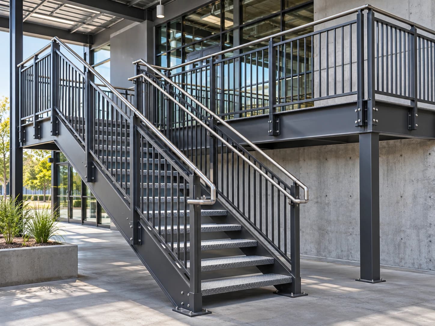
Fabrication & Submittal Coordination
Custom commercial railing runs, post anchorages, wall grab rails, and balustrade assemblies detailed to project contract specifications.
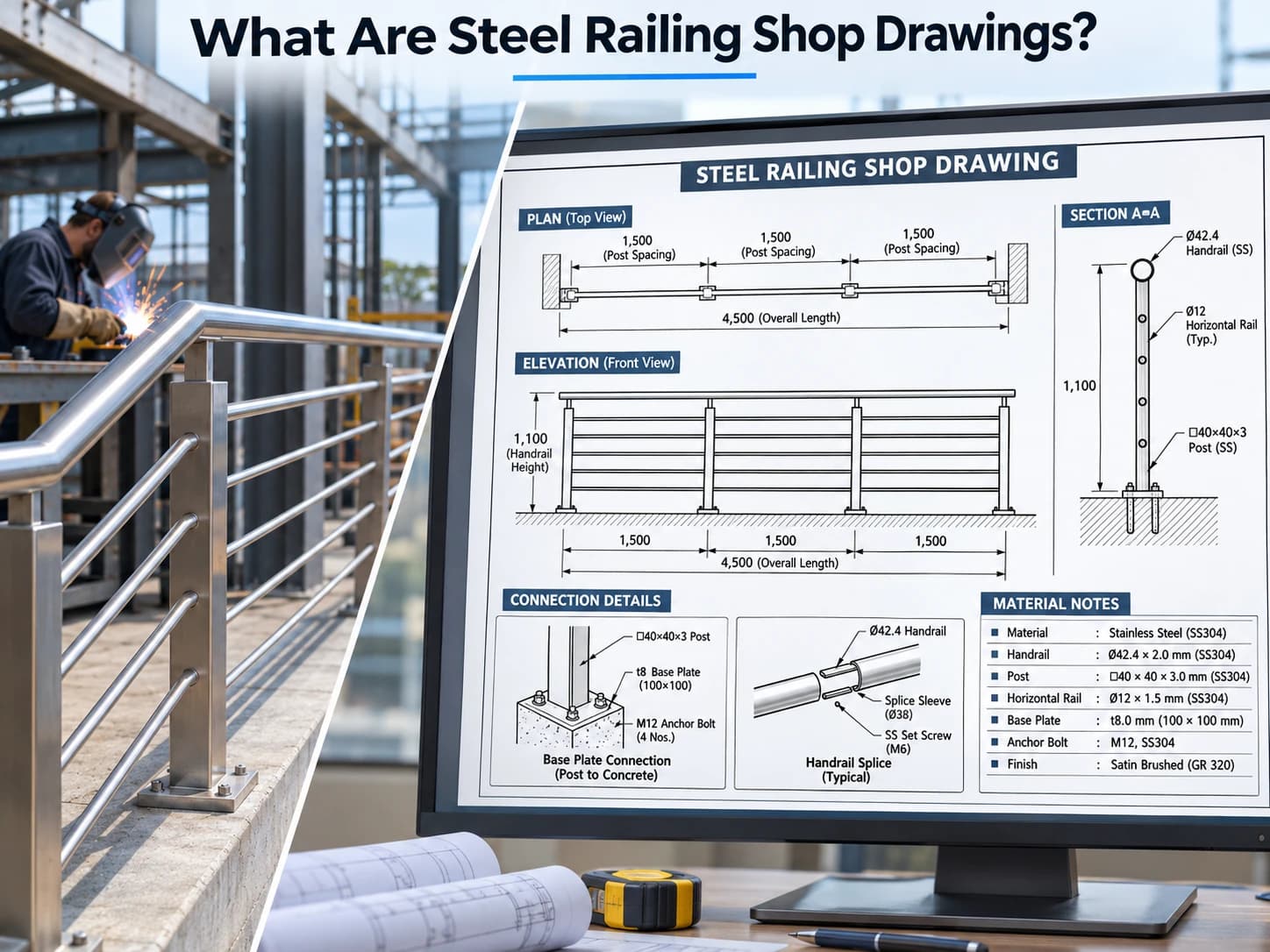
Design Intent vs. Shop Fabrication Documentation
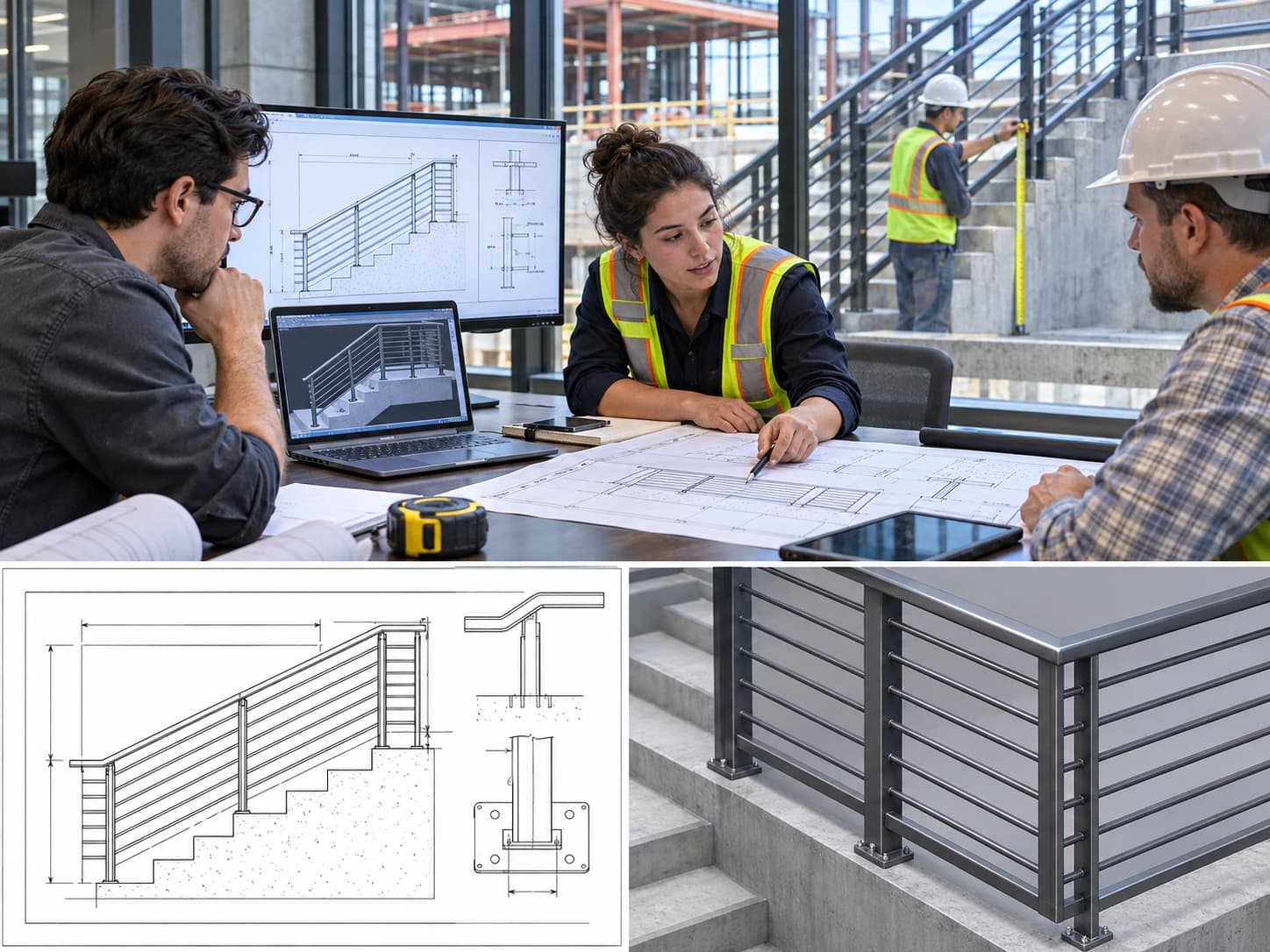
Illustration of a fabricated steel railing and the shop drawing information used to document a typical assembly.
Design Intent vs. Shop Fabrication
From Approved Railing Designs to Fabrication Documentation
Steel railing shop drawings translate the agreed architectural and structural requirements into coordinated information for an assigned railing fabrication package. A typical set identifies where each railing run begins and ends, its length and orientation, panel divisions, posts, horizontal or vertical members, transitions, attachment conditions and relevant material or finish information.
Architectural elevations express the intended appearance and performance criteria. Shop drawings develop the views, dimensions, parts and connection references needed to describe the approved assembly. They also expose questions that must be resolved before fabrication, such as conflicting slab edges, unclear wall backing, missing structural support criteria or a stair-rail transition that differs between plan and section.
Because a railing often connects to steel, concrete, masonry or a finished architectural surface, the setting-out information matters as much as the railing members themselves. A well-organized package helps the fabricator coordinate the work with the current design documents and helps the reviewer identify proposed assembly details. It does not transfer structural design responsibility to a drafting service.
Railing Applications
Shop Drawings for Common Steel Railing Applications
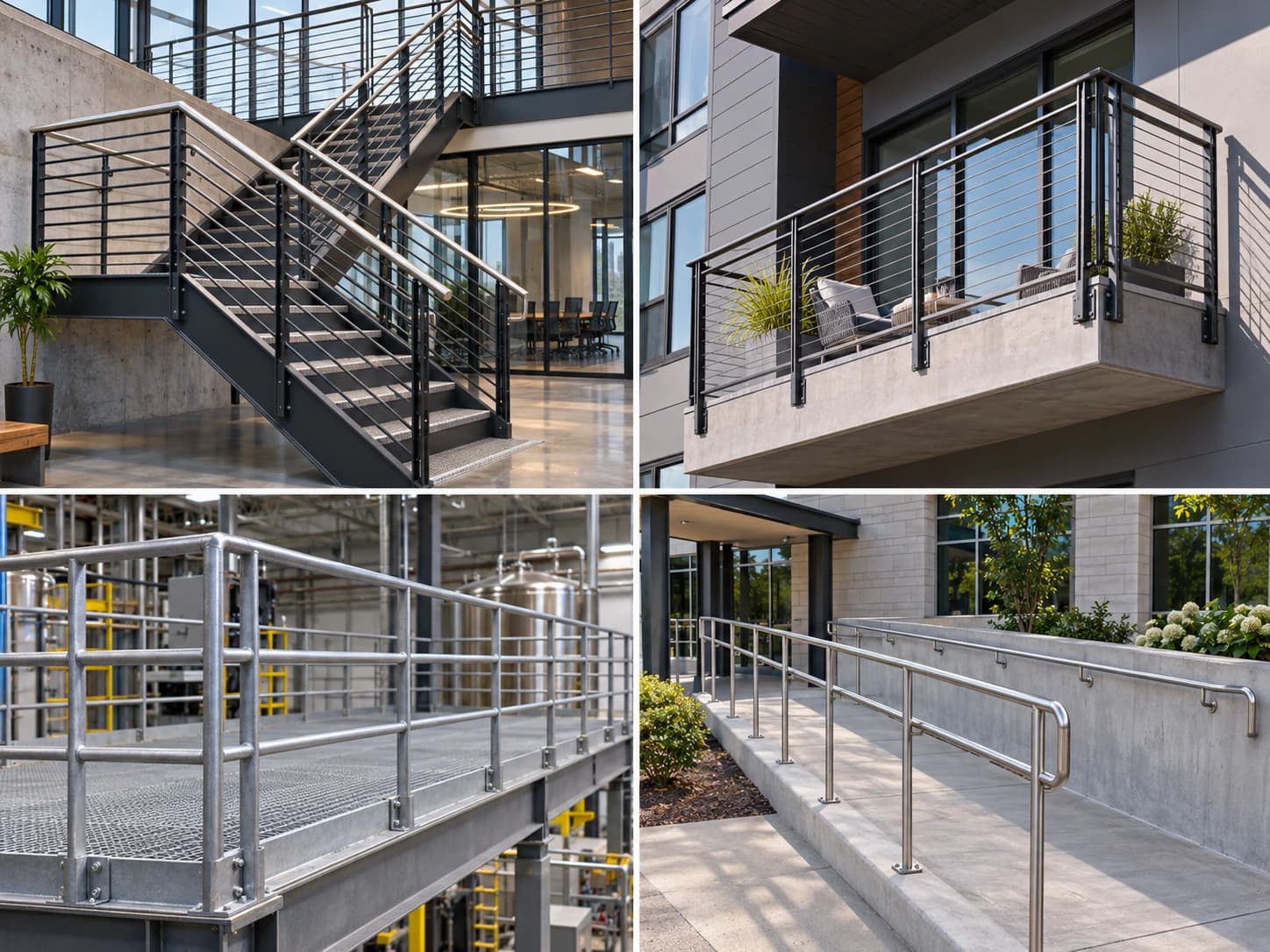
Railing dimensions, members, finishes and attachment methods depend on the building use and the approved system. The examples below show common applications within a railing detailing scope, not standard designs suitable for every project.
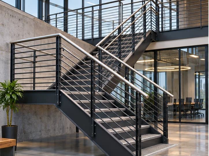
Stair Railings
Documentation for sloped railing runs, posts, landing transitions, stair-stringer interfaces and handrail coordination where included in the assigned work.

Balcony and Terrace Railings
Straight or segmented guard assemblies with elevation references, slab-edge conditions, panel joints and project-approved post anchorage details.
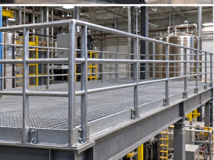
Industrial Platform Railings
Guardrail runs around catwalks, equipment platforms and access areas, coordinated with structural framing and applicable workplace requirements.
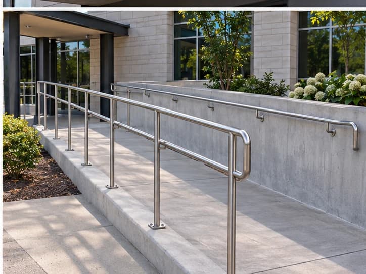
Ramps and Entrance Handrails
Wall- and post-mounted rail assemblies requiring continuous transitions, bracket locations, returns and coordination with accessibility requirements.
Coordinating stairs and primary steel framing alongside railings? Explore our dedicated Steel Stair Shop Drawings Page and Miscellaneous Metals Detailing Services.
Submittal Deliverables
What a Steel Railing Fabrication Drawing Package Includes
The number and format of sheets depend on the railing system and contract requirements. These are common deliverable categories used to document a railing package for review, fabrication and installation coordination.
| Deliverable | Typical Information |
|---|---|
| Railing layout plans | Rail runs, building references, post locations, panel marks, start and stop points |
| Railing elevations | Rail height references, slopes, post spacing, infill arrangement and joint locations |
| Sections and profiles | Rail shapes, post sections, mounting types and adjacent substrate conditions |
| Post and base plate details | Post-to-plate connections, approved anchor references, hole geometry and base locations |
| Rail splices and returns | Field joints, shop weld references, corner changes, handrail returns |
| Infill details | Pickets, intermediate rails, mesh or approved infill components |
| Material and part schedules | Part marks, specified material, lengths, quantities and finish references |
| Revision and submission records | Issue number, superseded sheets, authorized design-team comments |
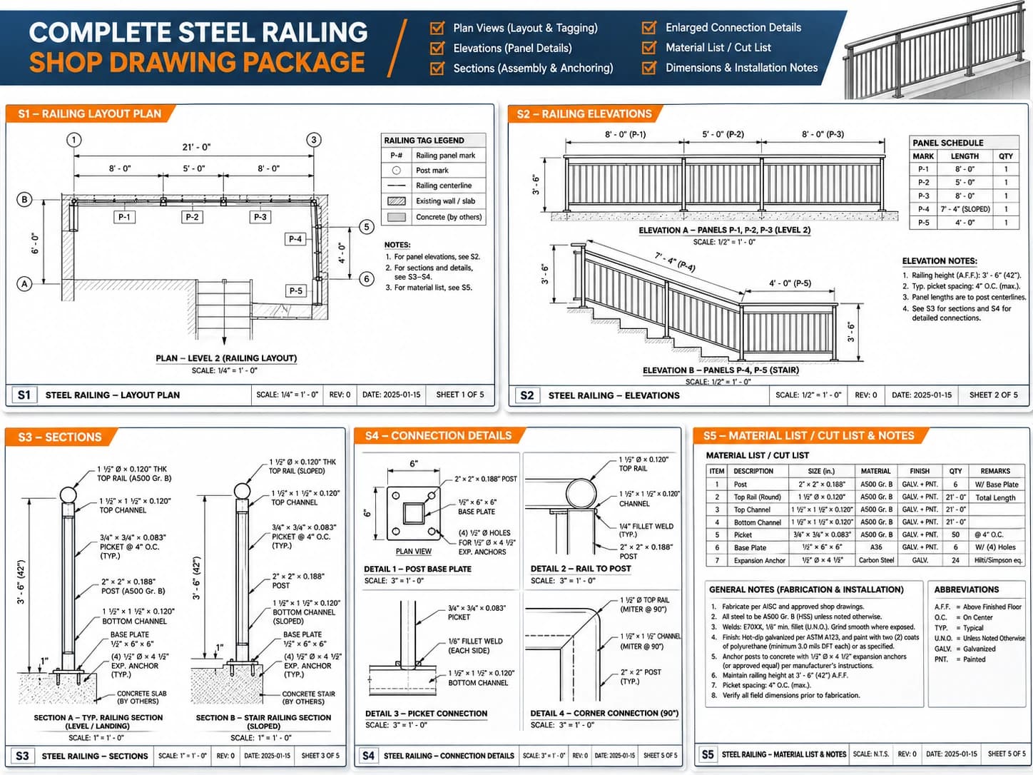
Schedules, editable CAD files, models and cutting data are included only where required by the agreed scope. Engineering calculations, professional stamps and project approval are separate responsibilities unless explicitly contracted with qualified professionals.
Setting Out & Divisions
Coordinating Railing Runs Before Fabrication
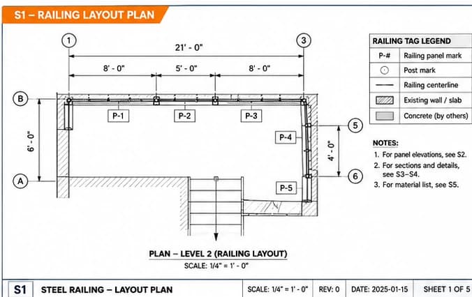
A railing layout plan identifies its relationship to project grids, walls, slab edges, stair openings and other architectural conditions. For multiple runs, a clear panel or piece-mark system connects a location on the plan to the matching elevation and fabrication details. The layout should distinguish level railings from sloping stair rails, returns and corners, with dimensions based on current approved drawings or verified field information.
Elevations explain each assembly's intended configuration. They can show post positions, top and intermediate rail locations, infill spacing, transitions, expansion or splice locations and marks for repeated panels. For a balcony or corridor, the drawing should identify which segments are straight, angled or curved, and whether adjacent finishes affect the mounting face or overall dimensions.
When existing construction is involved, missing field dimensions must be flagged for measurement rather than guessed. A marked field-verification list is often more useful than a completed-looking drawing built on incorrect assumptions.
Layout & Elevation Verification Checklist:
Railing Layout Plan & Grid Setting-Out
Railing Elevation & Panel Divisions
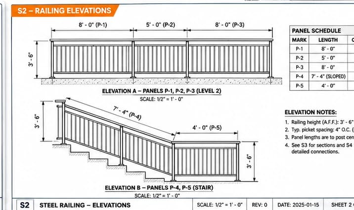
Illustrative only. Dimensions, fasteners and anchor design are not verified.
Attachment Coordination
Documenting Railing Attachments to the Building
The railing post and its support are frequent sources of submittal questions. Top-mounted posts, fascia-mounted brackets, steel-to-steel connections and other mounting arrangements require different information. A detail should identify the approved support material, post orientation, plate geometry, bolt or weld references, and any special coordination needed with waterproofing, concrete edge conditions or adjacent finishes.
Anchor selection and structural resistance are design matters. Rail shops should not infer anchor embedment, edge distance, reinforcement, steel weld size or allowable load from an illustrative internet detail. When those requirements are absent from the contract documents, the detailing set should clearly request the responsible design team's approved solution.
A well-presented railing connection package links post marks on the elevation to their corresponding approved attachment details. Where more than one attachment type is used, the drawing index and detail references should distinguish them clearly.
Connection specifications—including bolt grades, weld sizes, anchor embedment, and engineering calculations—must be provided in the approved design documents and verified by the designated project engineer.
Sloping Assemblies & Transitions
Coordinating Steel Railings Along Stairs and Landings
A stair railing follows a changing elevation, and the adjacent stair layout influences the final rail geometry. Railing drawings may need to show the sloping top rail, intermediate members, posts attached to stringers or landings, transition fittings and any separately specified graspable handrail. A continuous handrail and a protective guard are different functions, even when both appear in one assembly.
The contract drawings determine the required heights, clearances, returns, extensions and support criteria. The drafting package should make those approved requirements visible and identify unresolved conflicts. It should not substitute default dimensions from an unrelated residential, industrial or commercial setting.
At stair-to-landing transitions, special attention may be required around post positions, headroom, slab or stringer clearances, handrail continuity, and adjacent architectural finishes. These interfaces should be reviewed against both the stair package and the assigned railing scope.

Field Stair Assembly
Real-world commercial stair railing layout
Coordinated CAD Detail
Sloped elevations & post brackets
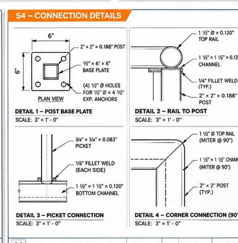
Splices & Joints
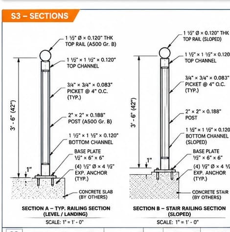
Member Profiles
Component-Level Detailing
Component-Level Detailing for Fabrication
Railing fabrication involves more than the overall guard outline. Depending on the selected system, the package may include round or square rails, HSS posts, pickets, intermediate rails, mesh or perforated panels, end caps, brackets and joints. The drawings must distinguish component types and communicate their fabrication relationships without introducing unapproved material or geometric changes.
Panel divisions and splice locations often reflect the shop's fabrication process, shipping constraints, coating requirements and the site's access conditions. Their positions must remain compatible with the approved architectural intent and any structural or code constraints. Shop welds and field connections should be distinguished clearly where this affects production or installation.
Specified finishes deserve coordination as well. Galvanized, painted, powder-coated and stainless-steel assemblies have different requirements for preparation, exposed appearance and field repairs. The final drawings should reference the actual project finish schedule and system details, not assume one finish for every steel rail.
Regulatory Criteria & Scope Boundaries
Why Railing Detail Requirements Change by Project
A guard is intended to protect the edge of an elevated walking surface. A handrail provides a graspable support along a stair or ramp. A workplace guardrail system may be subject to different criteria from a guard serving a public building. Those terms should not be treated as interchangeable on a fabrication submittal.
For example, the model International Building Code includes requirements for guards and handrails in Chapter 10, while OSHA 29 CFR 1910.29 sets separate criteria for covered general-industry walking-working surfaces and stair rails. Accessibility standards may impose additional requirements on the relevant route. The legally applicable rules depend on the location, occupancy, system function, adopted code edition and project specifications.
The drawing team's role is to document the specified and approved design criteria, identify discrepancies and send unresolved compliance or structural questions to the responsible design professional. A drafting service cannot guarantee code approval based on an unverified drawing, and sample images must never be used to establish code dimensions.
Governing Technical Reference Sources
Primary standards referenced for commercial and industrial railing coordination:
Section 1014 Handrails and Section 1015 Guards criteria.
Workplace guardrails, handrails, and stair rail systems.
Handrail extensions, graspable diameters, and clearances.
Structural steel and miscellaneous contracting standards.
Educational reference panel only. Does not assert regulatory pre-approval.
Sample Submittal Sheets
Illustrative Steel Railing Drawing Samples
The following conceptual sheets show common ways a steel railing package may organize elevations, component references, mounting conditions, sections and material information. They help explain the types of deliverables discussed on this page, but they are not actual past-project submittals.
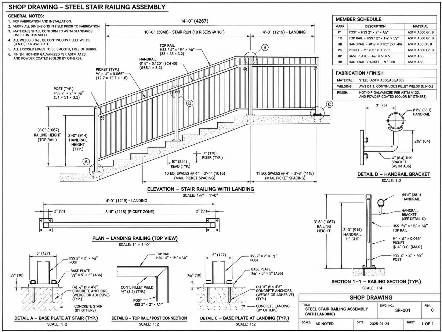
STAIR & LANDING ASSEMBLY SHEET
Scale: 1/2" = 1'-0"Stair and Landing Railing Assembly
A conceptual stair-rail assembly with landing transition, member references, handrail detail and post interfaces.
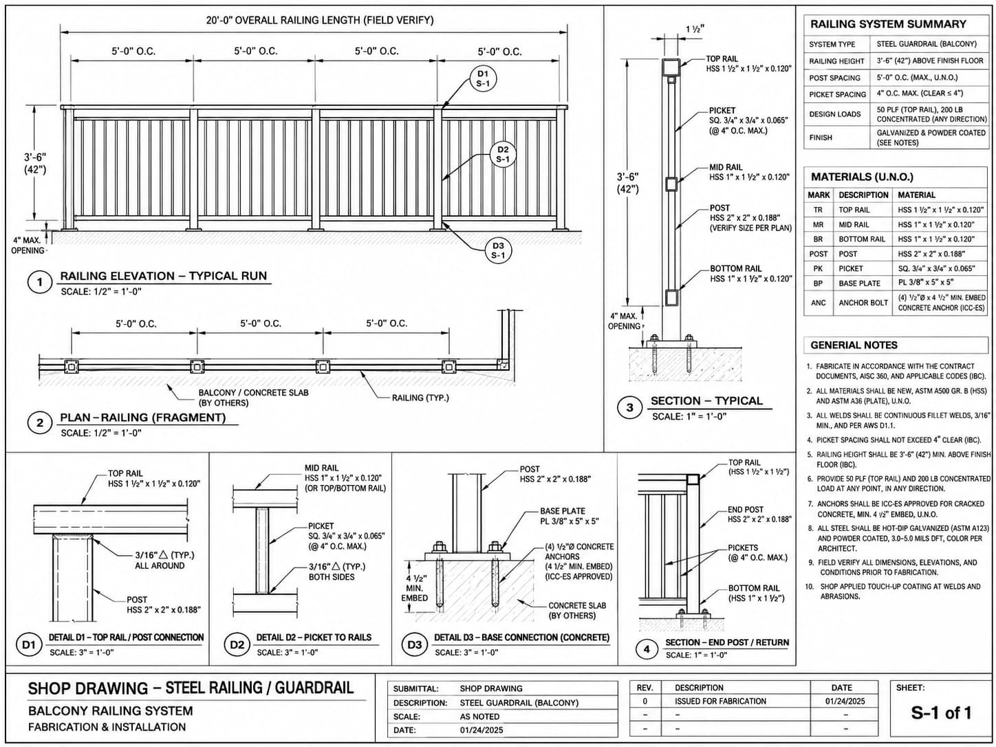
BALCONY GUARDRAIL SUBMITTAL SHEET
Scale: 3/4" = 1'-0"Balcony Guardrail Submittal Drawing
A hypothetical balcony guardrail drawing showing a typical level run, posts, sections and component references.
POST ANCHORAGE & CONNECTION SHEET
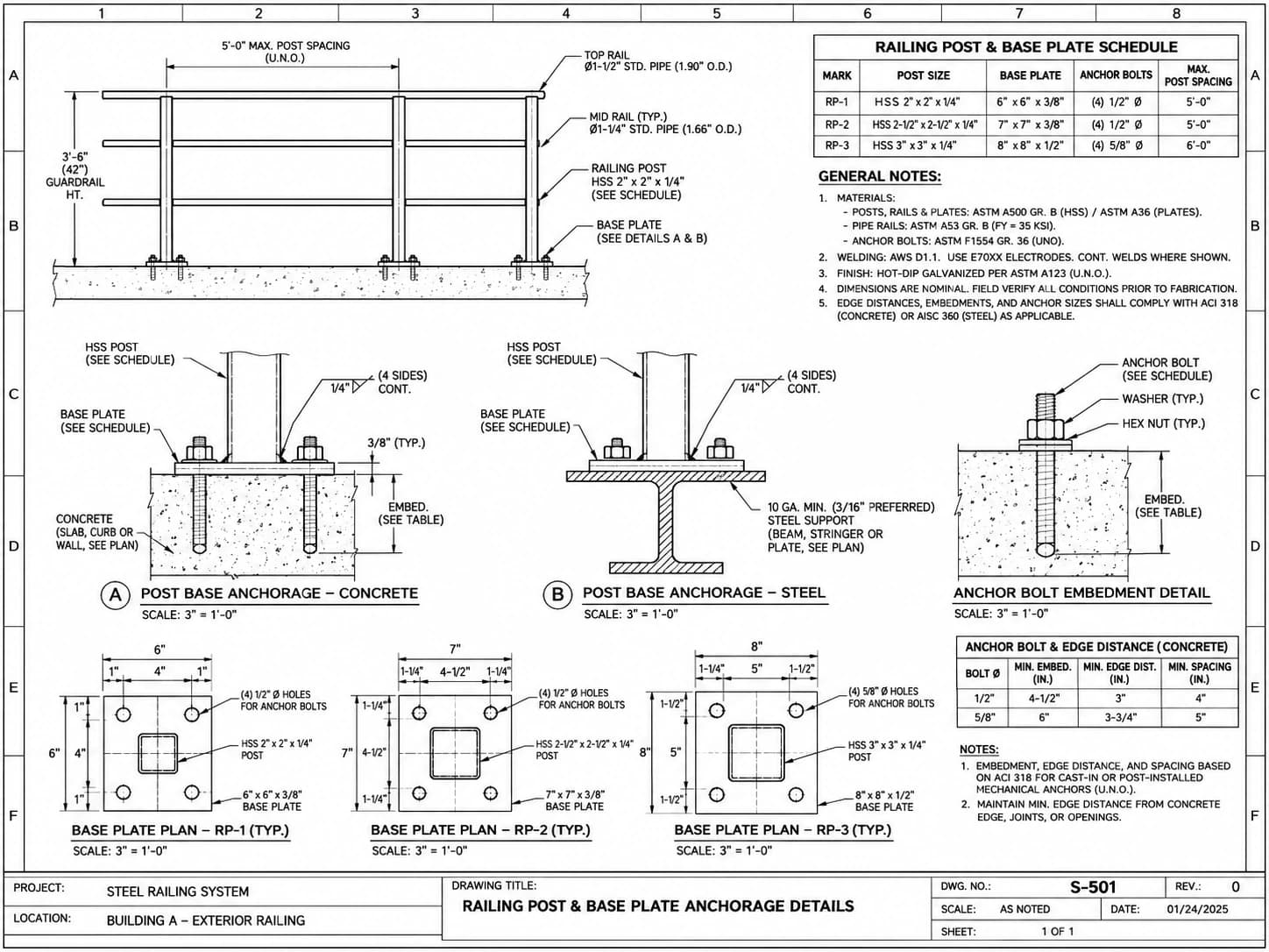
Scale: 1-1/2" = 1'-0"Post Anchorage and Base Plate Details
Illustrative post mounting concepts for concrete and steel support conditions. No connection shown is an approved engineered design.
FABRICATION & COMPONENT DETAIL SHEET
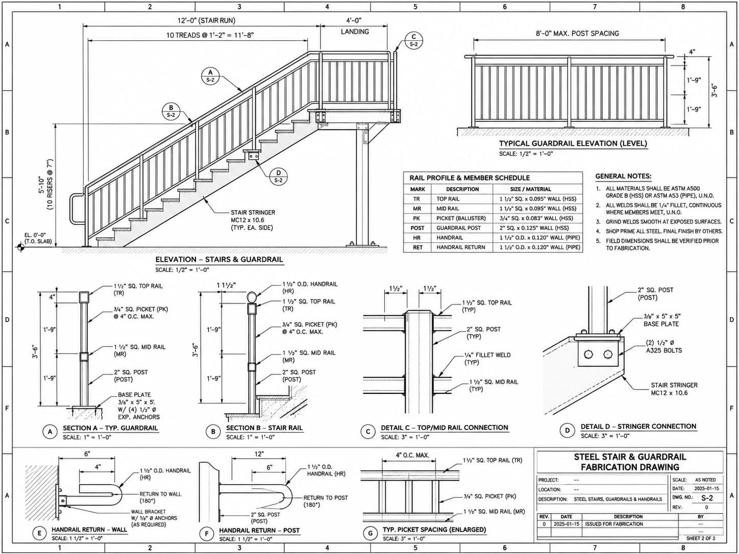
Scale: 1/2" = 1'-0"Steel Stair and Guardrail Fabrication Sheet
An illustrative fabrication drawing combining stair/landing guardrail elevations, member references and connection views.
Quotation Preparation
What to Send for a Steel Railing Shop Drawing Quote
A useful request identifies which railing runs are in scope and supplies the current documents that govern their design. For buildings with several floors or many repeated panels, mark the relevant rail schedules or locations so the quantity and complexity of unique assemblies are clear.
Missing substrate information, rail profiles or connection designs may require clarification before fabrication-level sheets are completed. Send the available package first so the actual scope can be reviewed.
Step-by-Step Workflow
From Source Documents to an Organized Railing Submittal
Our structured detailing procedure keeps project teams aligned from initial plan review through final fabrication release.
Review Rails
Establish railing locations, types, contract drawings, specifications and agreed deliverables.
Identify RFIs
Record unclear run lengths, slab-edge conditions, missing post designs and finish interfaces.
Prepare Sheets
Develop layout plans, elevations, piece marks, approved connection references and schedules.
Check & Submit
Reconcile marks, sections, interfaces and revision references for the defined review stage.
Incorporate Revisions
Process documented design comments, identify revised sheets and issue agreed final files.
The design team, fabricator and contractor continue to hold their respective contractual responsibilities for review, approval, fabrication, site measurements and installation. No schedule or approval guarantee applies without project-specific agreement.
Interface Verification
Railing Details That Deserve a Second Check
Small discrepancies between railing drawings and surrounding construction can cause costly field clarification. The most useful drawing-stage review focuses on interfaces that are difficult to resolve after fabrication.
| Coordination Issue | Possible Effect | Practical Drawing Response |
|---|---|---|
| Post mark differs between plan and elevation | Incorrect panel or support placement on site | Reconcile each run and part mark before fabrication release |
| Slab edge or wall substrate is unclear | Incomplete or conflicting anchorage at post base | Request approved support and edge distance information via RFI |
| Stair slope and rail geometry disagree | Misaligned posts or awkward handrail transitions | Compare railing elevations directly with current stair flight drawings |
| Actual field dimensions differ from architectural plans | Panel length or corner misfit during erection | Flag field verification dimensions and revise authorized sheets |
| Finish buildup changes mounting face elevation | Incorrect stand-off distance or base plate elevation | Coordinate relevant finished flooring and wall construction layers |
| Shop and field joints are not identified | Fabrication or installation ambiguity for oversized runs | Document authorized splice and shipping attachment locations |
| Revised architectural detail is overlooked | Superseded rail configuration fabricated by shop | Track the current contract document issue against revisions |
| Guard and graspable handrail are conflated | Missing required grab rail features or code non-compliance | Clarify intended rail functions and project design criteria |
Checking Protocols
A Drawing Package Built Around Clear References
Before releasing a railing drawing set for its agreed review stage, the information should be checked for consistent run identification, agreement between plans and elevations, complete dimension references, correct use of current contract revisions and clearly recorded outstanding coordination questions.
A useful internal check also compares post/base-plate references, rail profile information, infill schedules and selected finishes between related sheets. The drawing index and revision history should identify which drawings replace earlier issues, especially after an authorized architectural or structural change.
These document checks improve communication but do not constitute structural engineering, code certification or independent site inspection. Any unapproved connection design or critical missing information must return to the responsible design team.
Learn more about our checking procedures on our dedicated Quality Assurance Page.
Deliverables & Compatibility
Drawing Formats and Component Schedules
PDF drawing sets are commonly used for reviews, approvals and issue tracking. Depending on the agreed workflow, editable DWG or DXF files, relevant 3D models, component lists and other CAD exports may also be provided. A client should identify the required software format and any fabricator-specific naming or file standards when requesting a quote.
Material lists may describe member marks, sections, quantities, lengths, finish references and hardware categories. They should follow the approved design and scoped documentation rather than substitute for a verified structural design or fabrication quality procedure.
CNC, DXF cutting data, connection calculations, engineering seals and proprietary manufacturer system details must not be described as standard inclusions. Provide them only when specifically available and contractually agreed.
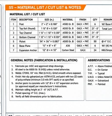
Conceptual material schedule; example entries are not verified project quantities.

Vector PDF
Submittal Booklets & Shop Prints

AutoCAD .DWG
Editable 2D CAD Layouts

DXF Profiles
Plate & Component Profiles

IFC 3D BIM
Open BIM Model Coordination

3D Isometric Views
3D Perspectives & Visuals

CSV / Excel Schedules
Material & Cut Lists
Review the complete software platforms we support on our Supported Detailing Software Page.
Audience & Application
Railing Drawing Support for US Construction Teams
Steel and specialty-metal fabricators use coordinated railing drawings to plan assemblies and understand component and attachment information. General contractors use them in submittal coordination and to reconcile the railing scope with stairs, slabs, building finishes and construction sequencing. Specialty subcontractors rely on the current drawings to identify their assigned fabricated runs and installation interfaces.
Steel & Misc Metal Fabricators
Organize shop cutting, fitting, hole punching, welding, and finish coatings from clear component drawings and material lists.
General Contractors
Reconcile railing scope with stair openings, slab edges, wall backing, and municipal code inspection milestones.
Railing Subcontractors
Verify site erection sequencing, field post anchorages, continuous grab rail transitions, and expansion joints.
Architects & Engineers
Review submittals against architectural design intent, sightlines, structural reactions, and egress safety codes.
Proposal Estimation
What Affects Steel Railing Shop Drawing Cost?
The effort required for a railing drawing package depends on the number of unique runs, total assembly variation, member and infill complexity, connection types, available information and the expected approval/revision process. Straight repeated rail panels normally require different documentation effort from sloped stairs, changes in direction, custom infill or complex slab-edge supports.
Additional considerations include whether field measurement is needed, whether the client requires a 3D model, the completeness of the design information, panel-break and shipment requirements, specified finish documentation and requested output formats. A fair quotation starts with the actual railing scope and current plans, not an arbitrary promise of a fixed price per sheet.
For related project budgeting, contractors may refer to construction cost estimating and material takeoff services where the paragraph discusses preconstruction quantities. This is a relevant estimating resource, not a claim that estimating is included in the railing drawing package.
Ready for a Project Estimate?
Share your architectural and structural sheets for an itemized, scope-based railing proposal.
Request a Scope-Based QuoteCommon Inquiries
Steel Railing Shop Drawings FAQs
Find answers to common questions about railing fabrication packages, deliverables, code boundaries, and submittals.
READY TO START YOUR RAILING DRAWING PACKAGE?
Need Steel Railing Shop Drawings for Your Next Project?
Send your latest plans, railing schedules, support details and requested deliverables. We will review the assigned steel railing scope and prepare a project-specific quotation.