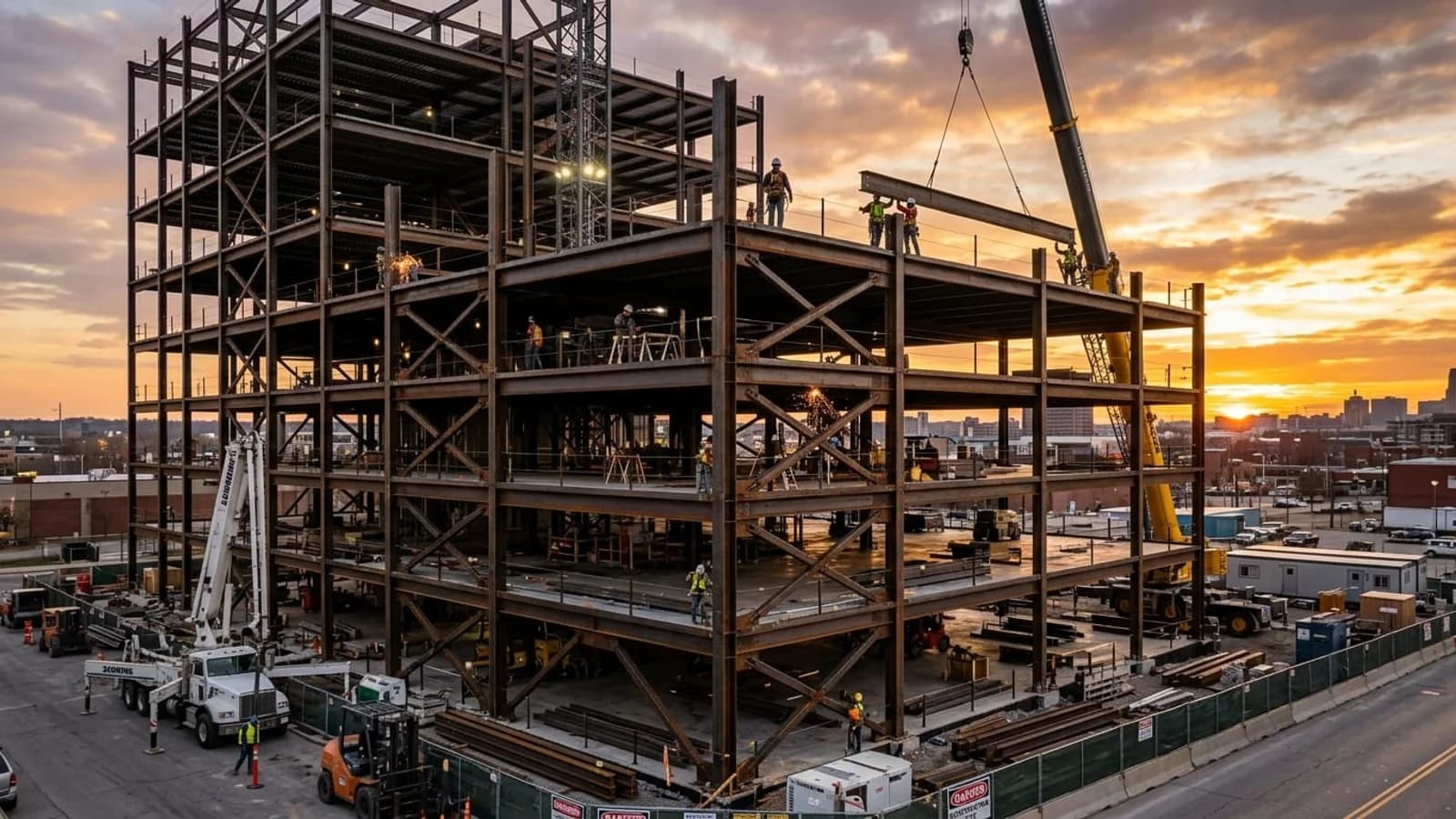
The short answer: name the system, prove the anchor, dimension the movement, and seal the perimeter as a system
Short answer: A curtain wall set is approved or returned on four questions. What system is this, a storefront, a curtain wall, or a window wall? Which anchor carries dead load and which carries only wind load, and how much adjustment does each allow? How much movement does each joint allow, thermal, building, and differential, and how much glazing bite is left at each extreme? Where does water go past the outer seal, and where does the perimeter seal stop air, water, fire, and smoke at the slab edge? Answer those four on the sheets, with schedules a reviewer can check, and the set moves. Leave one to a note that says "per manufacturer," and the set comes back, usually after glass has been ordered against an unapproved detail.
Who this is for: general contractors, facade and glazing subcontractors, architects, and reviewers who prepare or approve curtain wall and storefront shop drawings for commercial buildings in the United States.
Our glass facade detailing service prepares these packages the way a reviewer reads them: system first, then anchors, sections, movement, perimeter, and performance evidence.
System first: three different drawings
A wrong system name on the elevation is the most expensive sentence in a facade submittal. A storefront, a curtain wall, and a window wall look similar from the street. They do not anchor the same way, and they do not move the same way. Naming the system decides every detail that follows.
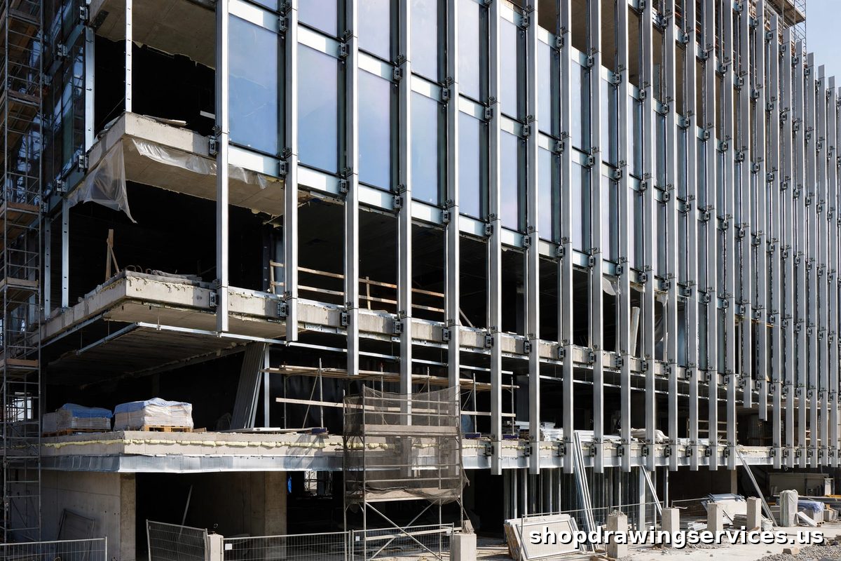
A storefront sits within a structural opening, typically at ground floor and about one storey high. It bears on the structure around the opening, and its wind load goes into that surrounding structure. A curtain wall hangs from the building, passes in front of the floor edges across multiple floors, is anchored at slab edges, and carries its own dead load down through its anchors floor by floor. A window wall sits between slabs, one storey at a time. Call a ground floor storefront a curtain wall and the set overstates the system. Detail a multi floor skin as a storefront and the set understates it, with no slab edge anchor schedule and no stack joint at each floor line. Where systems mix, the transition needs its own detail. The elevation must name the system, bay width, floor to floor height, and mullion span.
Anchors are the load path, not a bracket detail
Every curtain wall load, dead load of glass and framing plus positive and negative wind pressure, must reach the structure through an anchor. There is no other path. Yet anchor details often go vague: a typical bracket drawn once, no schedule, no distinction between dead load and lateral anchors, and no adjustment range. They can only approve a schedule tying every mullion bay to a specific anchor, embed condition, and adjustment range.
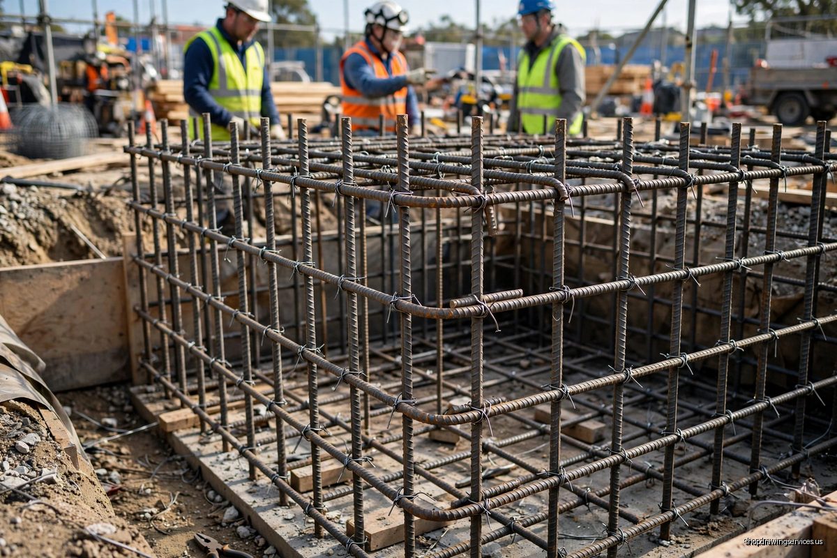
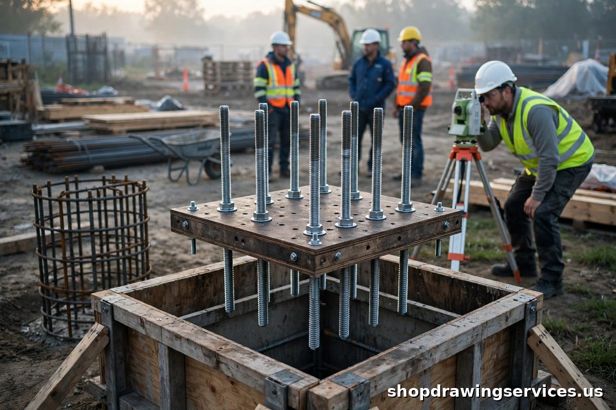
The common stick system arrangement makes the distinction concrete. One floor carries a combined gravity plus lateral anchor, holding dead load and resisting wind load. The next floor carries a lateral anchor only, resisting wind load but letting the mullion move vertically as building and frame move relative to each other. Sleeved or stack joints at floor lines take up that relative movement. If the drawings do not say which anchor is which, the erector cannot know where the frame is fixed and where it must stay free, and a frame fixed at both floors will bind, bow, or load glass edges never meant to carry load. A complete schedule shows, for every bay: mullion mark, anchor type, dead load, lateral load, or both, embed condition, adjustment range in three directions, and tolerance absorbed. Embed, channel, and bolted angle anchors each depend on the structure they land on, and no single type is universal. Slabs are not poured to shop tolerance, so the stated adjustment range, with the shims, slots, and bolts that deliver it, is what makes the anchor buildable. The parallel steel lesson is in our post on anchor bolt setting plans and the mistakes found only after the pour.
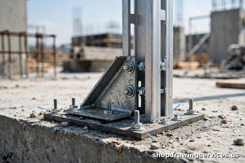
Artifact 1: anchor schedule excerpt (hypothetical bay set)
This table is hypothetical. Project values come from that project's structural drawings and facade specification, never a previous job.
Bay (hypothetical) | Dead load anchor | Lateral anchor | Embed condition | Adjustment |
|---|---|---|---|---|
Bay A, floor 2, typical | Combined gravity plus lateral anchor at floor 2 | Lateral anchor only at floor 3 | Cast in channel at slab edge, per structural drawings | As stated on the anchor detail, in three directions |
Bay B, floor 2, corner | Combined gravity plus lateral anchor at floor 2, corner condition | Lateral anchor only at floor 3, corner condition | Bolted angle to edge condition on the structural drawings | As stated on the anchor detail, in three directions |
Bay C, ground floor storefront | Not applicable, frame bears within the structural opening | Not applicable, wind load goes to the surrounding structure | Sill and jamb bearing on the structure around the opening | Shim and adjustment at sill and jambs, as detailed |
Mullions and sections: depth, thermal break, bite, and drainage
A mullion section must show depth, thermal break, glazing pocket, drainage path, and weeps, plus glazing bite remaining at both movement extremes. Depth is not a catalogue number. It is the depth keeping the mullion within the deflection limit the project specification sets for that span, under the design wind pressure established for that building under ASCE 7 as adopted by the project jurisdiction. Cite that project pressure and limit, not a pressure borrowed from another city or test report.
The thermal break matters twice: for energy, because unbroken aluminium is a thermal bridge, and for movement, because aluminium and glass do not expand at the same rate. A long mullion run grows measurably across a season, and the section must show where that growth goes: into a stack joint, a sleeved joint, or a sealant joint sized for movement, never into the glass edge. The pocket must stay deep enough that glass stays engaged at full contraction and does not bottom out at full expansion. Drainage completes the section: water past the outer gasket is collected in the pocket, drained through weeps outside, and the pocket is vented so pressure equalises instead of driving water further in. A section with no weep path assumes the outer seal never fails. Outer seals fail, and the drawing must show what happens next. The glazing schedule must tie to the same sections: glass build up, tempered versus laminated where required, panel marks, and panel size against the mullion deflection limit for that span. Stick systems need piece by piece sequence and field joints on the drawings; unitised systems need panel to panel joints, gasket continuity, and setting sequence instead.
Movement is three movements, not one joint
Reviewers read this section most carefully, and it is where sets most often cheat by drawing one generous joint and calling it the movement joint. Movement is three different movements, each needing its own dimension and check. Thermal movement of the framing: aluminium moves far more than glass for the same temperature change. Building movement: floor edge deflection, column shortening, creep, inter storey drift, and sway. Differential movement: the frame moving one way while the slab it hangs from moves another. A stack joint sized only for thermal growth will bind when the slab deflects. A joint sized only for drift will leak when the frame contracts in winter and the sealant joint opens beyond its capability. A joint taking all three at once, with no dimension for any separately, cannot be checked, and an uncheckable joint is a returned joint.
Dimension each movement separately, joint by joint, floor by floor. For each stack and sealant joint, show the thermal allowance, the building movement allowance, and the remaining glazing bite and sealant width at each extreme. The sealant joint, not the glass edge, must take the movement. At full contraction, the sealant must stay within its capability and the bite stay engaged. At full expansion, glass must not bottom out and sealant must not compress beyond its capability. Governing limits and temperature ranges come from the project specification and applicable AAMA document for that project. Our shop drawing services treat the movement schedule as a deliverable in its own right, because it predicts whether the facade will still work in its fifth winter.
Artifact 2: movement joint table (hypothetical floor to floor bay)
This table is hypothetical. Real values come from the project specification, structural movement criteria, and sealant movement capability.
Movement source (hypothetical bay) | Allowance shown | Check at the extreme |
|---|---|---|
Thermal movement of the mullion run | Dimensioned separately on the stack joint detail | Bite still engaged at full contraction; glass not bottomed out at full expansion |
Building movement, slab deflection and drift | Dimensioned separately on the stack joint detail | Stack joint still free to move; slab deflection does not load the frame below |
Differential movement, frame versus slab | Dimensioned separately, not merged into either allowance above | Sealant width stays within its movement capability at both extremes |
Perimeter seals are a system, not a bead of sealant
The perimeter is where the curtain wall meets the building, and where the most persistent failures live: leaks at the slab edge, air leakage at the head, water at the sill, and fire and smoke paths at the floor line nobody detailed because everybody assumed somebody else had. A detail showing only a sealant bead has not detailed the perimeter at all.
Inside the system, drained and vented glazing pockets, weeps, and pressure equalised chambers manage water past the outer gaskets. At the perimeter, backer rod and sealant at the slab edge, head, jamb, and sill manage water and air where the system meets the building. Each condition needs its own detail, because head, jamb, sill, and slab edge meet different substrates, move differently, and drain differently. A single typical detail copied to all four will be wrong at three of them. At the floor line, safing insulation and perimeter fire barrier treatment, where required, close the gap between slab and curtain wall against fire and smoke spread, under a listing covering that specific assembly. The United States test method for perimeter fire barrier systems is ASTM E2307, and listing, safing material, compression, and inspection all belong on the detail. Each perimeter detail should also show substrate preparation, backer rod size, sealant type and joint width, and the drainage path away from the joint.
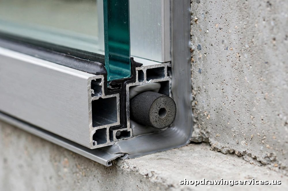
Artifact 3: perimeter seal checklist, before submittal
Slab edge: sealant and backer rod sized on the detail; safing and fire barrier treatment shown as a separate line with its listing, where required; drainage path shown.
Head: sealant joint dimensioned for movement; substrate preparation noted; head checked against slab deflection above.
Jamb: sealant joint dimensioned; backer rod size stated; transition to adjacent wall construction detailed, not left to the field.
Sill: sealant joint dimensioned; sill drainage and weep path shown; sill checked against ponding and foot traffic where applicable.
Every condition: sealant, backer rod, safing where required, and drainage each have their own line to tick. A sealant-only condition is not ready to submit.
Performance evidence belongs on the drawing, not in a brochure
A submittal should let the reviewer match every performance claim to a detail. The current methods document is AAMA 501-24, Methods of Test for Exterior Walls. As referenced in AAMA 501-24, laboratory methods include ASTM E283/E283M-19 for air leakage, ASTM E331-00(2023) for static water penetration, and ASTM E330/E330M-14(2021) for structural performance by uniform static air pressure difference. Dynamic water penetration is covered by AAMA 501.1, field water testing by AAMA 501.2, and seismic and drift performance, where required, by AAMA 501.4 and AAMA 501.6. Field evaluation, where specified, is addressed through AAMA 502, AAMA 503, or AAMA 511 as applicable.
What matters is the pairing: each cited test, the project required pressure or rate, and the detail delivering it. Air leakage under ASTM E283 means nothing without the project rate and the gasket and perimeter details achieving it. Static water penetration under ASTM E331 means nothing without the project pressure and the drainage details managing water at that pressure. Structural performance under ASTM E330 means nothing without the project pressure and the mullion depth and anchor schedule resisting it. A set claiming a system "passes" a test the project never specified, or quoting a pass pressure from another project's report, has provided marketing copy, not evidence. Likewise, a laboratory mockup passing does not prove every installed perimeter seal is continuous, which is why field water testing under AAMA 501.2 exists, and why drawings should show where field testing will be done.
The seven step check, in the order a reviewer works
System first: storefront, curtain wall, or window wall, named on the elevation, with the span and anchor logic that follows.
Anchor schedule: every bay, dead load versus lateral anchor, embed condition, adjustment range, and tolerance.
Sections: depth, thermal break, glazing pocket, bite at both extremes, drainage, and weeps.
Movement schedule: thermal, building, and differential movement dimensioned separately, joint by joint, floor by floor.
Glazing schedule: glass build up, tempered versus laminated where required, and panel sizes against the mullion deflection limit.
Perimeter details: head, jamb, sill, and slab edge seals, backer rod, safing and fire barrier treatment where required, each as its own detail.
Performance block: each cited test matched to a detail, with the project required value, not a borrowed pass figure.
Run that check before submittal, and most returns become self corrections, cheap on paper and expensive after glass is ordered.
What to send with the submittal, so it gets approved the first time
Send the system named on the elevation, the anchor schedule, sections with bite at both extremes, the movement schedule with three separate allowances, the glazing schedule with panel marks, the four perimeter details, and the performance block with project required values. Send the source drawings and specification sections with it. Send questions early: where the slab edge condition is unclear, where structural movement criteria are missing, and where the fire barrier listing is not yet confirmed, ask before fabrication, not after.
If your next facade package is a curtain wall or storefront and the anchor, movement, or perimeter details are still open, send the drawings and specification before glass is ordered. Our team will check the set against the seven steps above, mark what is ready, and list what still needs a project value. Start with our contact page and tell us the system, floor to floor height, and slab edge condition. Those three facts decide most of the detailing that follows. See our quality assurance process, covering the two stage review every set goes through before it leaves the office.