The short answer: the schedule must match the drawing, or nothing gets cut
Short answer: A bar bending schedule is only safe to fabricate from when every bar mark, size, shape and length in it matches the placing drawing, and both match the structural design. If they disagree, stop and resolve it on paper. Cutting first and asking later is how a pour gets a cage that does not fit, a lap that does not develop, or cover an inspector will reject.
Who this is for: general contractors, concrete subcontractors, rebar fabricators, detailers, and project managers who review rebar sets before fabrication release or before concrete arrives.
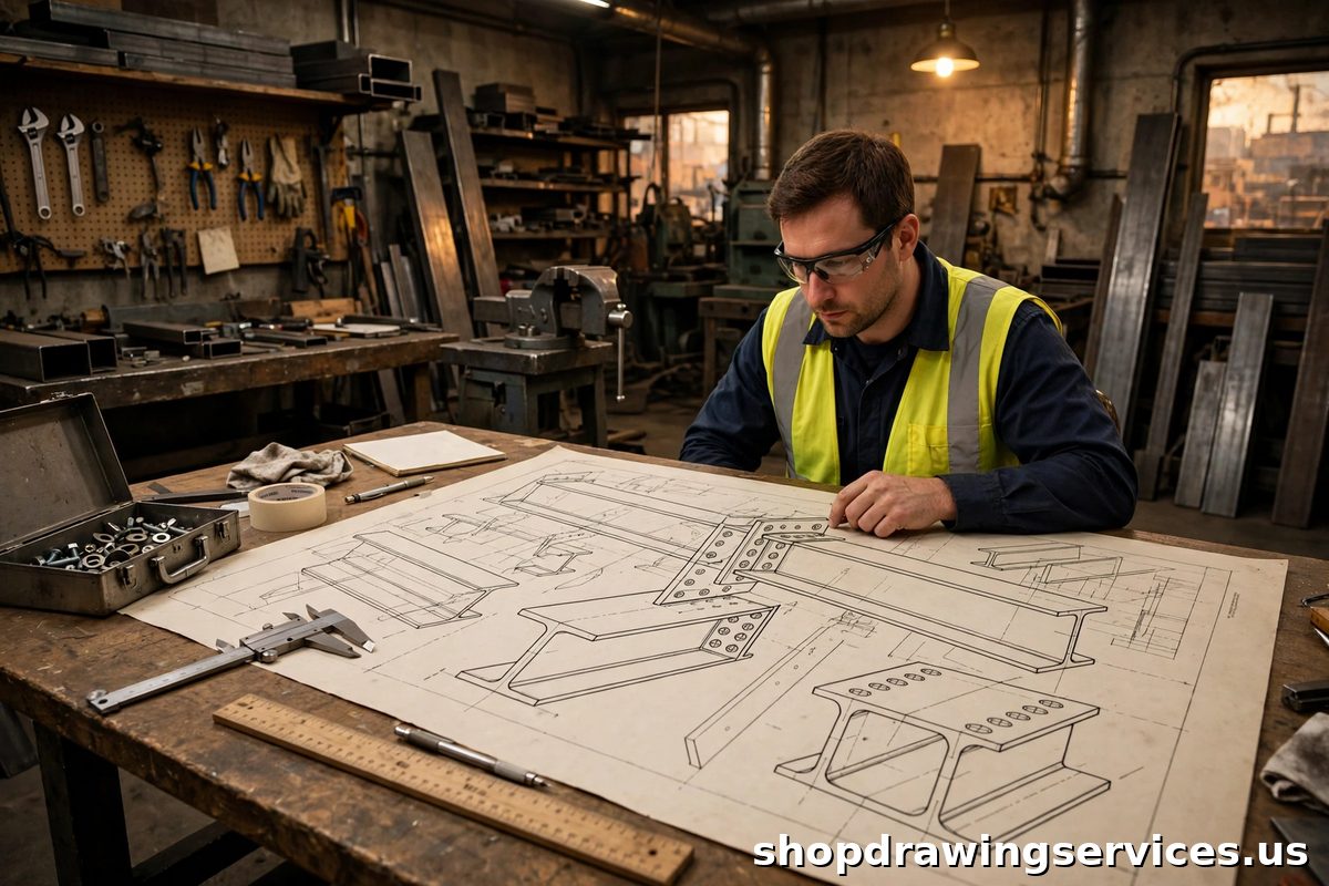
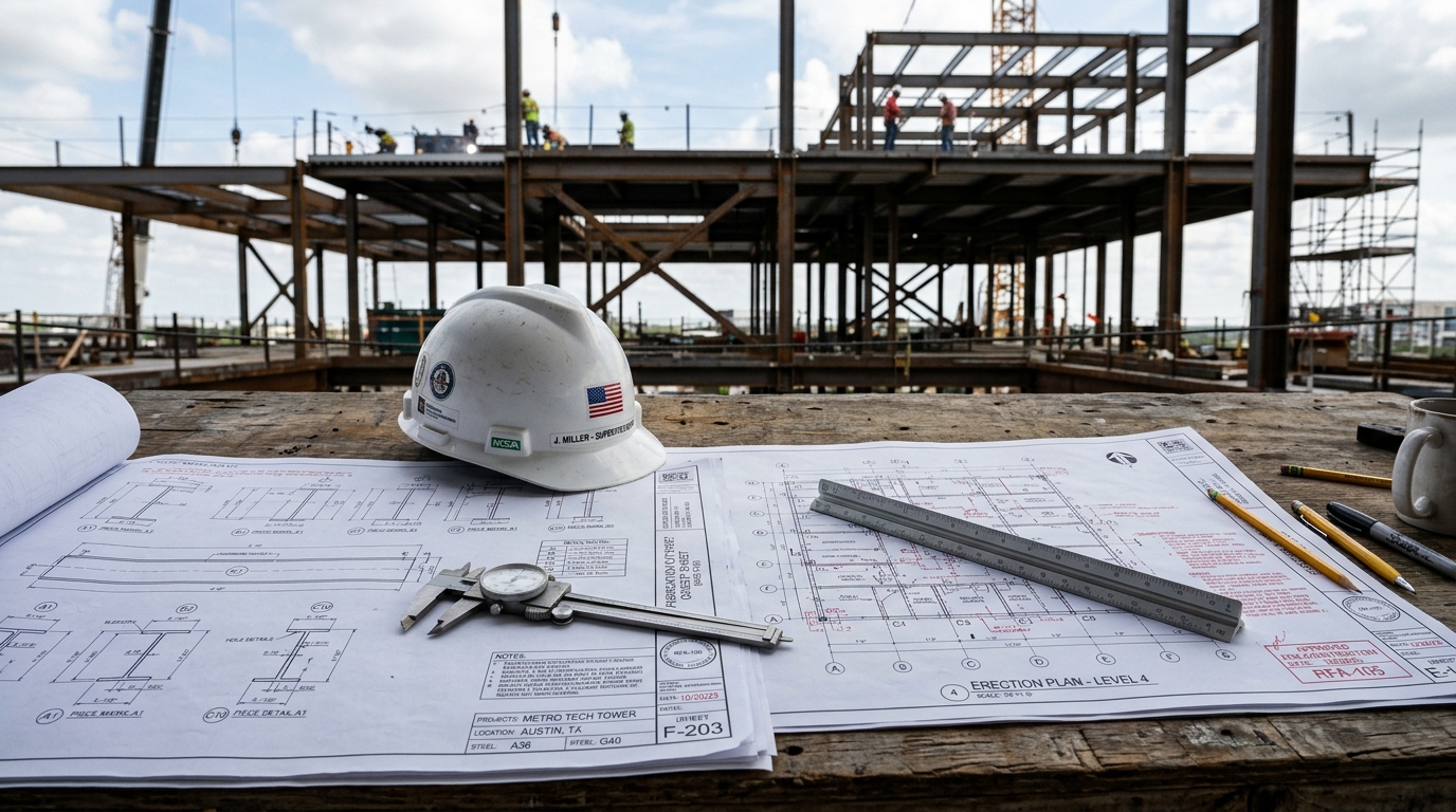
The structural design drawings say what the engineer designed. The placing drawings, also called rebar shop drawings, say how those bars are arranged in each member. The bar bending schedule, or BBS, says how each distinct bar is cut and bent in the shop. Our rebar detailing service produces placing drawings and schedules as one coordinated set, and our guide to shop, fabrication and erection drawings explains which set each party should work from. When those documents disagree, the pour is where it surfaces, and that is the most expensive place to find it.
Three documents, three jobs, one bar mark
Keep the three documents apart. The structural design drawings give bar sizes, spacing, cover, lap and development requirements, and locations. The detailer interprets them, and any gap or conflict is a question for the engineer of record, not a detail the shop may invent.
The placing drawing shows how bars are arranged in each member, in plan and in section, with bar marks, spacing, cover, laps, hooks, joints and pour sequence. Sections matter as much as plans. A bar that looks right in plan can fail in section, where development, cover, and congestion are visible. Check the worst section, not only the typical one.
The bar bending schedule is the fabrication table for each distinct bar. Each row needs a bar mark, size, shape sketch or shape code, bending dimensions, cutting length, quantity (members times bars per member), and total length and weight. The bar mark is the link between all three documents. The same mark on the placing drawing, in the schedule, on the bundle tag, and in the cage must mean the same bar. Use the schedule for verification, not discovery. It should confirm what the placing drawing already shows. Spot check bar lengths, quantities and hook dimensions against plan and section.
Read and check in this order
Work in this order, member by member, pour by pour.
1. Title block, revision and design basis first
Confirm you are checking an approved set, which code edition the project adopts, the bar grade, the concrete strength, and which sheets cover which pour. Never check a superseded sheet because it was the first one opened. Our structural steel submittal checklist makes the same revision point for steel, and it applies to rebar: a correct check of the wrong revision is still a wrong check.
2. Member by member, plan then section
For each member, confirm what member it is, what pour it belongs to, and what construction joint bounds it. Check continuity across joints and into adjacent members before checking any single bar. A bar that ends at a joint without the development or lap the design requires will not perform as designed.
3. Bar marks, used consistently everywhere
Trace one mark from the placing drawing to the schedule to the bundle tag. One mark must mean one bar shape, size and length. If the same mark appears with two lengths, hold fabrication for that bar until the detailer reconciles it. A size typo that survives to fabrication is easy to miss in two dimensional work and impossible to fix on site without reordering.
4. Spacing, cover and congestion
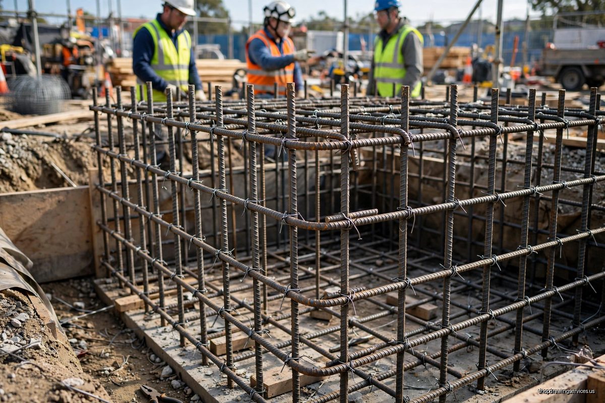
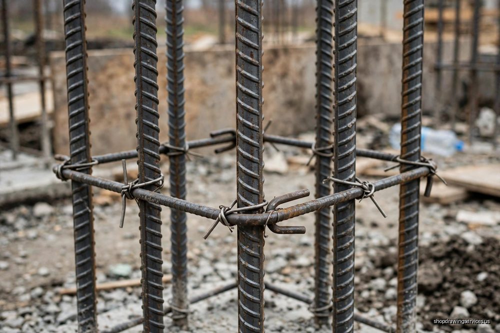
Bars too close together block concrete flow and vibration. Bars too far apart leave the member short of steel. Check clear spacing against the adopted code, cover for the member's exposure, and congestion where laps, hooks, embeds, sleeves and other trades meet. Cover is measured to the outermost reinforcement, ties and stirrups included, not to the main bar alone.
5. Laps and development
Check where laps sit, how long they are, whether they are staggered, and whether each bar has room to develop past the lap and into its support. A lap in a high stress zone, or every bar lapped at the same section, needs a design answer, not a field fix. Lap length is project specific: it depends on bar size, grade, concrete strength, spacing, location, and tension or compression. The structural drawings must state lap locations and lengths.
6. Hooks, bends and terminations
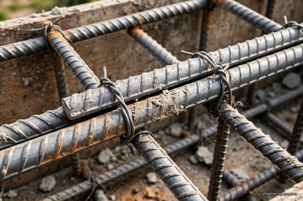
Check hook type and extension, bend diameter, and whether a stirrup or tie hook closes around a longitudinal bar. A 90 degree hook without its required extension, or a stirrup hook that does not enclose its longitudinal bar, is a detailing error. Where the project is in a seismic design category, hook requirements and splice restrictions change, and must be treated as design given items to check, never invented by the detailer.
7. Coordination and pour sequence
Check openings, sleeves, embed plates, anchor bolts, post tensioning ducts and mechanical, electrical and plumbing penetrations against the cage, and check for missing reinforcement around openings. Confirm what is placed in which pour, in what order. A clash found after cages are tied forces cutting or moving bars on site, which weakens the work and delays the pour.
The errors that cost pours
Most rebar failures at the pour trace back to a small set of paper errors.
- Schedule and drawing disagree. A mark, size, shape or length in the BBS does not match the placing drawing. Fix on paper, mark by mark, before fabrication release.
- Cutting length wrong. Outside dimensions added without bend deductions, or hook allowances missed. Fix: show the deduction method used, and spot check one bent bar per shape by hand.
- Lap length copied, not checked. A lap from another project, or a flat rule of thumb, used where code, size, grade, strength, spacing and location require a project specific length. This post publishes no flat lap table. Lap length comes from the project drawings.
- Lap location wrong. Laps where stress is highest, or all laps at one section, instead of staggered and clear of high stress zones as the design requires.
- Cover and spacing missed. Cover for the wrong exposure, or spacing not achievable once laps and hooks are tied in. Check the worst section, not the typical one.
- Wrong bar, right mark. A size typo that survives to fabrication. Fix: verify size against the design schedule, not the previous sheet.
- Missing bars and missing scope. Bars omitted around openings, at joints, or at member ends. Fix: a member end and opening checklist per member.
- Coordination clashes. Rebar drawn in isolation from sleeves, embeds and other trades. Fix: clash check against architectural, structural and mechanical models before reinforcement arrives.
Concrete cover: ACI 318-19, Table 20.5.1.3.1
Concrete cover protects reinforcement from corrosion and fire, and provides the bond that lets steel and concrete work together. The values below are from ACI 318-19, Table 20.5.1.3.1, for cast in place, nonprestressed reinforcement, verified at publish time. Your project may adopt a different edition, and project specifications may require more than the code minimum. The project adopted edition and specifications govern.
| Exposure | Member | Reinforcement | Specified cover |
|---|---|---|---|
| Cast against and permanently in contact with ground | All | All | 3 inches |
| Exposed to weather or in contact with ground | All | No. 6 through No. 18 bars | 2 inches |
| Exposed to weather or in contact with ground | All | No. 5 bar and smaller | 1.5 inches |
| Not exposed to weather or in contact with ground | Slabs, joints, and walls | No. 14 and No. 18 bars | 1.5 inches |
| Not exposed to weather or in contact with ground | Slabs, joints, and walls | No. 11 bar and smaller | 0.75 inch |
| Not exposed to weather or in contact with ground | Beams, columns, and pedestals | Primary reinforcement, stirrups, ties, spirals, and hoops | 1.5 inches |
Cover is measured to the outermost reinforcement, so a tie or stirrup that sticks out past the main bar sets the cover, not the main bar. "Exposed to weather" is a project condition, not a guess: a slab edge or wall face that will see weather or ground contact takes the weather row, even if the rest of the member is interior.
Laps, large bars, and bundles: what CRSI and ACI 318 actually say
Development length and lap splice length sit in ACI 318 Chapter 25. The engineer must indicate lap splice locations and lengths on the structural drawings, per the Concrete Reinforcing Steel Institute (CRSI) lap splice guidance. If a lap location or length is missing from the design drawings, the review question is not "what length should we use?" It is "why is it missing, and who will supply it?"
Large bars have a hard limit. Lap splices of No. 14 and No. 18 bars should not be used, except in compression only to No. 11 and smaller bars. That is CRSI guidance consistent with ACI 318, which does not permit tension lap splices for bars larger than No. 11 because of limited test data for large bar laps. A schedule that laps a No. 14 bar in tension is an error to return.
Bundled bars follow a related rule. Lap splices of bundled bars are based on the lap length for individual bars of the same size, individual splices within a bundle should not overlap, and the lap length is increased 20 percent for a three bar bundle and 33 percent for a four bar bundle, per CRSI. Do not lap an entire bundle as one unit.
Where bars of two sizes are lap spliced, CRSI practice is specific. In tension, use the larger of the tension lap splice length for the smaller bar, or the tension development length for the larger bar. In compression, use the larger of the compression development length of the larger bar or the compression lap splice length of the smaller bar. The splice is governed by the more demanding bar, never by the smaller one alone.
A US practice trap: metric sizes, foreign shape codes, and flat lap rules
Several secondary schedule guides use metric bar sizes, BS 8666 shape codes, and flat lap rules such as 40d or 50d. Those are not ACI 318 values, and must not be imported into a US schedule. A schedule built on another country's shape codes and lap rules is a fabrication error waiting for a US inspector.
The test is simple. If a guide gives you a lap length without asking for bar size, grade, concrete strength, spacing, location, and tension or compression, it is not giving you an ACI 318 lap length. It is giving you a shortcut, and the inspector checks the project drawings and the adopted code, not that guide.
Sources are listed in the references below.
Artifact 1: BBS trace table (hypothetical marks only)
Use this table shape on any rebar review. One row per distinct bar. The match tick is the whole point: placing drawing mark equals schedule mark equals bundle tag, or the row does not release. All marks and lengths below are hypothetical (*), and no real project data is used.
| Member and pour | Bar mark | Bar size | Shape reference | Cutting length | Bars per member | Members | Total quantity | Match tick |
|---|---|---|---|---|---|---|---|---|
| Beam B1, Pour 2 | 101 | No. 8 | Straight, hooks both ends | 24 ft 6 in* | 4 | 6 | 24 | Yes |
| Beam B1, Pour 2 | 102 | No. 4 | Closed stirrup | 6 ft 2 in* | 18 | 6 | 108 | Yes |
| Wall W2, Pour 3 | 201 | No. 6 | Straight, lapped | Schedule 18 ft 0 in*; drawing 19 ft 4 in* | 12 | 2 | 24 | No: stop, do not cut |
Row 201 is the deliberate mismatch. The action is not to pick the number that looks more likely. Stop, query the detailer, and hold cutting for that mark until the two documents agree.
Artifact 2: Pre-pour rebar check (printable)
Run this list before concrete arrives, member by member. An empty box is the list of open items, and concrete should not cover an open item that affects strength, cover, or development.
- Revision current, approved set for this pour.
- Bar marks consistent across drawing, schedule, and bundle tags.
- Spacing achievable once laps, hooks, and ties are in.
- Cover correct for the member's exposure, to outermost reinforcement.
- Lap locations and lengths as drawn by the engineer, staggered where required.
- Hooks closed around longitudinal bars, with required extensions.
- Reinforcement present around openings, member ends, and joints.
- Embeds, sleeves, anchor bolts, and penetrations coordinated against the cage.
- Pour sequence and joints agreed, each pour's bars identified.
- Bundle tags readable after handling, matched to member and pour.
Artifact 3: Lap quantity arithmetic (hypothetical only)
Counting laps is where quantity errors hide, because a lap is easy to count once per cage when it should be counted once per bar line. The arithmetic below is hypothetical, and the lap length itself comes from the project drawings, never from this example.
Example: a single bar line needs one lap per bar because stock length is shorter than the member run. That adds one lap length per bar line, not one lap per cage. Count: 10 bar lines times 1 lap each equals 10 laps, each at the project lap length stated on the structural drawing. If miscounted as one lap for the whole cage, the schedule understates lap steel by 9 laps. Multiply per bar line, check per member, and total per pour.
What to send, and what a review is not
When you send a rebar set for review, send the placing drawings, the bar bending schedule, and the design drawings or notes the set was built from, with revision and pour identified for each sheet. A schedule sent alone cannot be verified, because verification means checking it against the drawing. A drawing sent without its schedule cannot be fabricated.
Shop drawing review verifies that detailing matches design intent and code. It does not transfer responsibility for means and methods, and it is not a redesign. A reviewed stamp is not approval for construction without coordination. If a lap, hook, cover value, or bar size is missing or in conflict, the correct next step is a written question to the engineer, answered before steel is cut, not a field decision made after cages are tied.
If you have a rebar set that needs this check before fabrication release or before a pour, send it through our contact page with member, pour, and revision identified. A set checked mark by mark, section by section, and lap by lap is a set that pours right the first time.
References
- American Concrete Institute, ACI 318-19, Table 20.5.1.3.1 (cover) and Chapter 25 (development and splices). The project adopted edition governs.
- Concrete Reinforcing Steel Institute, "Lap Splices," https://www.crsi.org/reinforcing-basics/reinforcing-steel/splicing-bars/lap-splices/
- STRUCTURE magazine, "A Practical Guide to Reviewing Rebar Shop Drawings," https://www.structuremag.org/article/a-practical-guide-to-reviewing-rebar-shop-drawings/