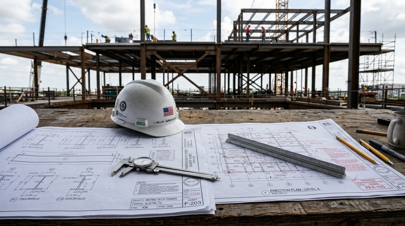
The short answer: check the setting plan while it can still be fixed
Short answer: An anchor bolt setting plan is the last drawing that can still be wrong cheaply. Once concrete is placed, a misplaced anchor group, a short projection, a rotated embed plate, or a missing sleeve is no longer a drawing correction. It is a field fix, an engineered repair, or a delayed column. Check the setting plan while the template is still on the formwork, not after the crane is waiting for a column that will not fit.
Who this is for: general contractors, concrete subcontractors, steel fabricators, erectors, detailers, and project managers reviewing foundation interface drawings before a pour or before steel arrives.
A setting plan is a setting instruction for the concrete crew, not a design calculation. It tells the crew where each group and plate goes, how it is held, and how far each rod must project above finished concrete. Our structural steel detailing service produces setting plans as part of a coordinated steel package, so groups agree with the base plates they will receive. When setting plan, base plate drawing, and rebar drawings disagree, the pour is where it surfaces, and that is the most expensive place to find it.
Three drawings, three jobs: setting plan, embed plan, base plate
Each document answers a different question, and a mistake in any one of them breaks the same joint.
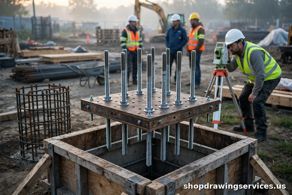
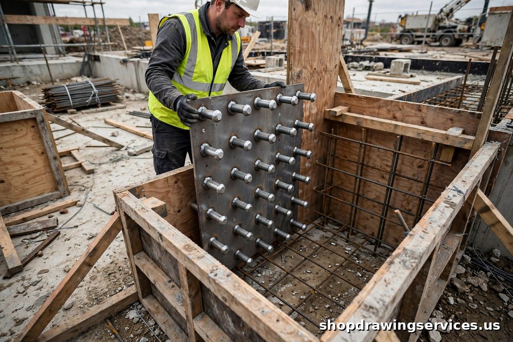
First, the anchor bolt setting plan: where each group sits, on which gridlines, with group dimensions, bolt size and grade, projection above finished concrete, embedment below, and the template holding the group during the pour. It shows the group in elevation too.
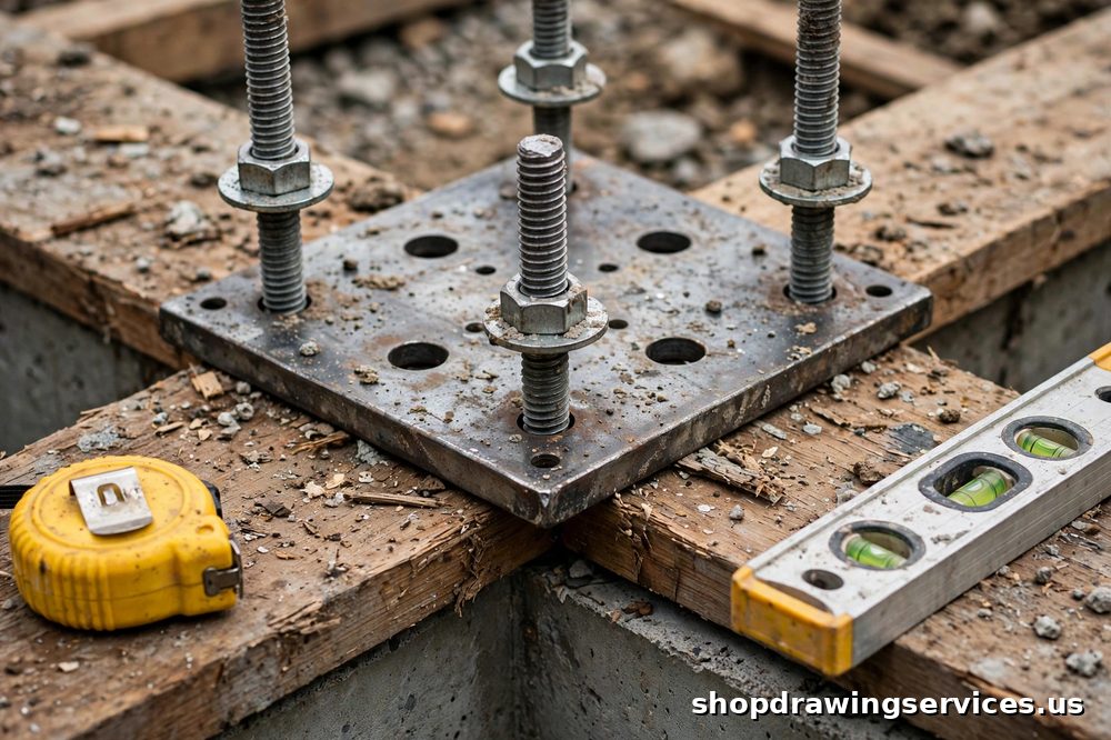
Second, the embed plate setting plan: where each plate sits, its size, studs or anchors, orientation, elevation and edge distances, and what it connects to later: a beam seat, a brace, a facade bracket, a stair stringer. A plate drawn without its later connection gets set backwards or at the wrong elevation, noticed only when the connecting member arrives.
Third, the base plate and column interface, the steel side of the same joint. Hole sizes, washer sizes, leveling nut and grout space, and the column line must all agree with the setting plan. If the group does not match the holes, the column does not erect. Our guide to steel connection detailing mistakes covers the connection side.
The practical rule is simple: no anchor group is approved on its own, only when the setting plan, the embed plan, and the base plate drawing all describe the same joint, on the same gridlines, at the same elevation, with the same bolt size and grade.
How to read and check a setting plan, in order
Work through a setting plan in this order. Do not skip ahead to bolt spacing before grid control is settled. Most setting errors are found in the first two steps.
- Title block, revision, and grid control first. Confirm this is the approved set, or a clearly marked review set, and which gridlines and column lines govern. Confirm the benchmark and elevation datum, and that it matches the survey datum. A setting plan checked against a superseded grid, or a different datum from the survey, is wrong before any bolt is measured. Our structural steel submittal checklist covers the revision checks that apply here.
- Group by group, plan then elevation. For each group, check its location on the grid, bolt spacing within the group, group to group spacing, and group to column line. Then check diagonals: equal diagonals prove a rectangular group, unequal diagonals prove a skewed group that a tape check on spacing alone would miss. Check the elevation view for the same group, so projection and embedment are confirmed together.
- Projection and embedment. Check threaded length above finished concrete, with enough thread past the nut and washer after leveling and grout are allowed for. A bolt long enough in total but short above concrete after grout and leveling is a short bolt in practice. The setting plan should show required projection as a minimum above finished concrete, with the grout and leveling allowance stated.
- Template and fixity. The template, plywood or steel, must match the base plate holes and be tied to formwork or to the rebar cage so concrete placement cannot move it. Threads must be protected from splash, and rods must be plumb. A template held by hand, or a group tied only to loose rebar, will move during the pour.
- Coordination before the pour. Overlay the setting plan on the rebar drawings, sleeve and conduit layouts, post-tensioning ducts, and other embeds at the same pier or footing. A group that clashes with a cage, a sleeve, or a duct must be resolved on paper, not by bending a bolt after concrete. Our rebar shop drawing guide explains how bar marks, laps, and cover are checked before the pour.
- Survey after setting, before the pour, and again after the pour. Position, elevation, and plumb must be recorded, not assumed. A pre-pour survey never repeated after placement misses the movement the pour itself caused, which is exactly the movement that matters.
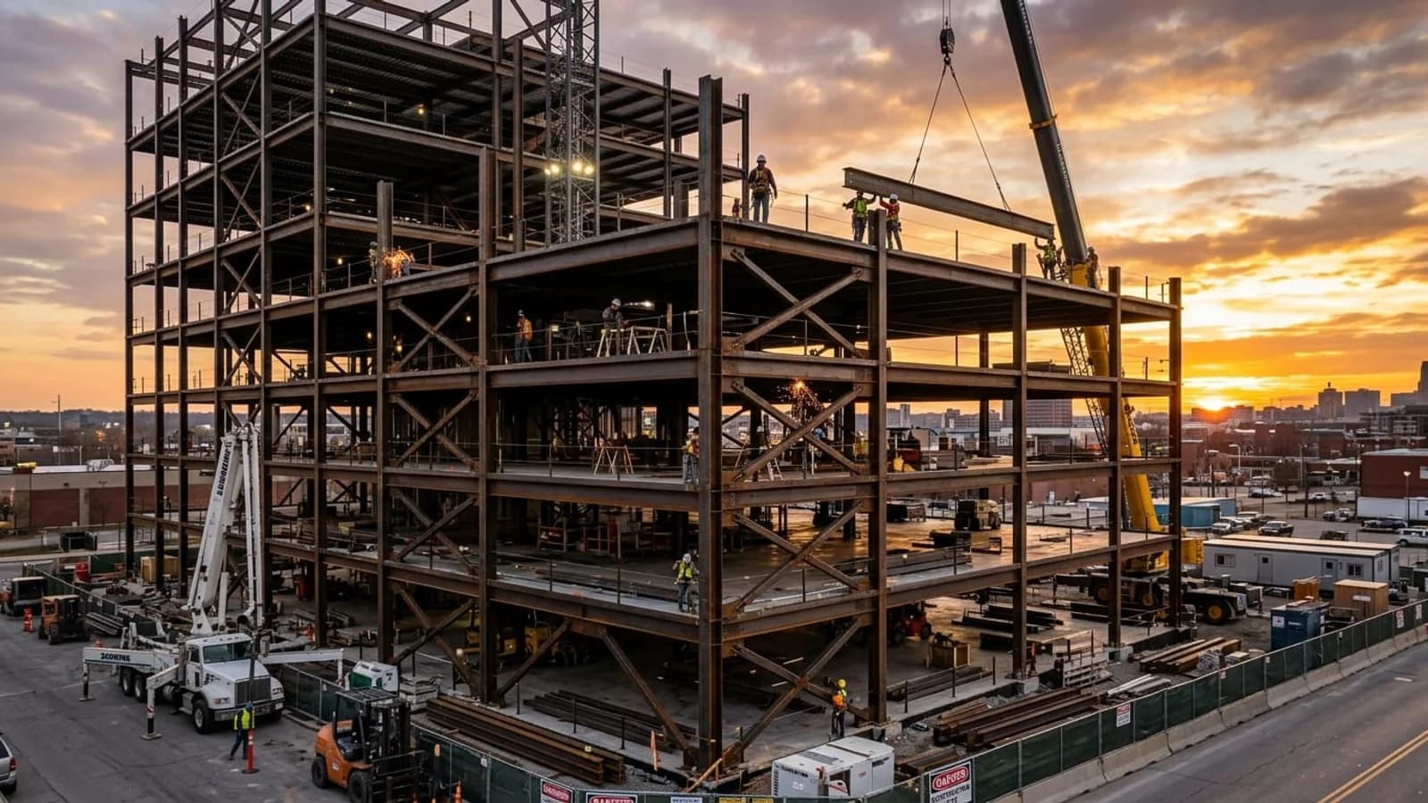
- Grout and erection readiness. Check grout space under the base plate, confirm leveling nuts are not left as the permanent load path, confirm grout is placed before the column is loaded as the design requires, and confirm holes and washers cover the holes at the as-built bolt positions. Our guide to reading a steel erection plan picks up where this post leaves off.
The tolerance trap: two industries, two tolerances, one joint
This is the central problem in anchor bolt setting, and it is a contract problem before it is a field problem. The steel and concrete industries publish different tolerances for the same anchor rods, and each trade normally works to its own standard unless the project specifications say otherwise.
AISC 303, Code of Standard Practice for Steel Buildings and Bridges, Section 7.5, sets tight tolerances: within a group, 1/8 inch or less between centers of any two rods; between adjacent groups, 1/4 inch or less; rod top elevation, plus or minus 1/2 inch; accumulated variation along a column line, 1/4 inch per 100 feet, maximum 1 inch total; group center to column line, 1/4 inch or less. Confirm the edition adopted for the project; do not assume values from a summary.
ACI 117, Specifications for Tolerances for Concrete Construction and Materials, differs. For embedded items generally, it allows a centerline deviation of plus or minus 1 inch. For individual anchor bolts, Section 2.3.4.2 gives tolerances by diameter: plus or minus 1/4 inch for 3/4 and 7/8 inch bolts, plus or minus 3/8 inch for 1, 1-1/4, and 1-1/2 inch bolts, plus or minus 1/2 inch for 1-3/4, 2, and 2-1/2 inch bolts. On plumb, ACI 117 states no tolerance, while AISC treats plumb strictly, with effectively no slack for a leaning rod. The two standards broadly agree only on top elevation.
The American Society of Concrete Contractors, in Position Statement 14, proposed a compromise: plus or minus 1/4 inch for 3/4 and 7/8 inch bolts, plus or minus 3/8 inch for 1 to 1-1/2 inch bolts, plus or minus 1/2 inch for 1-3/4 to 2-1/2 inch bolts. That is a contractor recommendation, not a code, and not a substitute for a specification naming the governing tolerance.
Oversize holes and plate washers absorb small misplacements, but not a group set to the looser tolerance when holes were sized for the tighter one. The check is therefore not "is this within some tolerance" but "is this within the tolerance the holes and washers were sized for." If the specifications name no governing tolerance before the pour, that blank is itself the finding, to be raised as a question, not discovered when a column does not fit.
Artifact: tolerance comparison table
Use this table on every project, with the project specification column filled in before the pour. If that column is blank, the project has not yet decided, and the groups should not be set until it is.
| Tolerance type | AISC 303, Section 7.5 | ACI 117, individual anchor bolts | Project specification (governing value) |
|---|---|---|---|
| Within a group, between centers of any two rods | 1/8 inch or less | By diameter, see below | Fill from project specification |
| Between centers of adjacent groups | 1/4 inch or less | Assembly centerline plus or minus 1 inch | Fill from project specification |
| Group to established column line | 1/4 inch or less | By diameter, see below | Fill from project specification |
| Top elevation of rods | Plus or minus 1/2 inch | Compatible with AISC on elevation | Fill from project specification |
| Accumulated variation along a column line | 1/4 inch per 100 feet, maximum 1 inch total | Not stated in same form | Fill from project specification |
| Plumb | Strict, effectively no slack | No plumb tolerance stated | Fill from project specification |
| Individual bolt location by diameter | Covered by group tolerances above | 3/4 to 7/8 in.: plus or minus 1/4 in.; 1 to 1-1/2 in.: plus or minus 3/8 in.; 1-3/4 to 2-1/2 in.: plus or minus 1/2 in. | Fill from project specification |
Sources: AISC Code of Standard Practice (AISC 303), Section 7.5; ACI 117, Section 2.3, including Section 2.3.4.2 for individual anchor bolts; ASCC Position Statement 14 for the compromise values. Confirm the edition adopted for each project before relying on any value here.
The mistakes found only after the pour
Each mistake below is followed by the check that catches it while it is still cheap. Work through them against the setting plan, not from memory on site.
1. Group set to the wrong grid, or mirrored
Reading a group dimension from the wrong column line, or mirroring a left-right pair, puts the group where no base plate can reach it. Fix: survey from established column lines, check diagonals, confirm handedness for mirrored bays.
2. Template moved during the pour
A group tied to loose rebar or held by hand shifts under concrete pressure and vibration. Fix: rigid template fixed to formwork, re-survey after the pour as well as before it.
3. Projection short
Threaded length is eaten by a high pour, a thick grout bed, leveling nuts, and washers, leaving too few threads past the nut. AISC Design Guide 1 recommends threaded length beyond the minimum, to allow for setting variation. Fix: show required projection as a minimum above finished concrete, with grout and leveling allowance stated, and protect threads from splash.
4. Rotation and orientation
A plate or asymmetric group set rotated 90 or 180 degrees looks finished until the connecting member finds its holes, studs, or seat on the wrong side. Fix: orientation mark on plan and template, named later connection for every plate.
5. Edge distance lost
A group too close to a pier edge, a joint, or another embed loses cover or washer bearing. Fix: check edge distance on the plan, not only bolt spacing, against every nearby embed at the same pier or footing.
6. Coordination clash cast in
A group through a sleeve, conduit bank, cage corner, or post-tensioning duct is a clash concrete makes permanent. Fix: overlay the plan on rebar, MEP, and structural plans before formwork, resolve every clash on paper.
7. Wrong rod, right position
Grade or diameter swapped between groups, for example Grade 36 set where Grade 55 was specified. Fix: grade and diameter on plan and group tag, checked group by group, not by shipment.
8. Field fix without an engineer
Torch slotting a base plate, cold bending a bolt, or welding a washer to cover a misplaced group are not crew decisions. A field modification to a base plate or anchor group is an engineered repair needing design approval first. Design Guide 1 notes washers should not be welded to the base plate except where rods are designed to resist shear at the column base.
Artifact: pre-pour setting check
Run this checklist against the setting plan and on site, before concrete is ordered. An empty box is still useful: it is an open item before concrete arrives.
- Revision current; set in hand is the approved set, or a clearly marked review set
- Gridlines, column lines, benchmark, and datum confirmed with survey
- Group dimensions checked, group by group, with diagonals checked for skew
- Projection above finished concrete checked, with grout and leveling allowance stated
- Template rigid, matching base plate holes, fixed to formwork or cage
- Threads protected from splash, rods plumb
- Rod grade and diameter checked group by group against plan and group tag
- Edge distances checked against pier edges, joints, nearby embeds
- Rebar, sleeve, conduit, post-tensioning overlay clear, clashes resolved on paper
- Embed plate orientation marked, named later connection for every plate
- Pre-pour survey recorded, post-pour survey scheduled before erection
- Governing tolerance named in the specification; holes and washers sized for it
Artifact: setting plan trace, one group from paper to concrete
All dimensions here are hypothetical, for teaching only. No real project's grid, group, or survey is shown.
Take one hypothetical group: four rods on a rectangular pattern at a single column, at a stated distance from two column lines, with a stated projection and grout allowance. Step one: check group dimensions and diagonals on the plan. The diagonals must be equal for a rectangular group. Here one diagonal measures 60 inches, the other 60-3/4 inches. The group is skewed, and a tape check on spacing alone would have missed it. Action: stop, re-set the group, do not pour.
Step two: build the template to match the base plate holes, fix it to formwork, check it against the same column lines. Step three: survey the group after setting and before the pour, recording position, elevation, and plumb. Step four: survey again after the pour and compare with the base plate holes and washers. Only when the as-built group fits, with the governing tolerance satisfied, is the column ready to erect.
What shop drawing review does not do
Review verifies detailing matches design intent and code. It does not transfer responsibility for means and methods, and it is not a redesign. A reviewed stamp is not approval for construction without coordination with rebar, sleeves, MEP, and survey.
What to send for a setting plan review
Send the setting plan with gridlines, group dimensions and diagonals, rod size and grade, projection and embedment, template details, embed plate sizes with orientation and later connections, edge distances, and the governing tolerance. Send the base plate drawing with it, so the reviewer can check the group against the holes it must fit, plus the survey datum and coordination overlay.
If a setting plan arrives without a governing tolerance, a template detail, or a named connection for an embed plate, send it back with those three questions first. They decide whether the column fits, and are cheapest to answer before concrete. To have a package checked as part of a coordinated steel set, contact our detailing team with the structural drawings, base plate details, and Division 3 and Division 5 sections.