
The short answer: read the right document, in the right order
Short answer: Start with the title block and revision, then the general notes and grid, then piece marks, then member orientation and sequence, and read connections last and slowest. Check every piece mark three ways: the mark on the erection drawing, the mark on the shop drawing, and the mark on the fabricated piece must all match before that piece is lifted. If a mark does not match, or cannot be read, quarantine the piece and ask. Never guess it into place.
Most erection day trouble does not start at the crane. It starts at the drawing table, when a reader opens the wrong document, reads a superseded sheet, or treats a piece mark as a size. An erection plan tells you where to put steel, but it does not tell you how to lift it, and a shop drawing tells you how a piece is made, but it does not tell you where it goes.
Who this is for: steel erectors, ironworker foremen, general contractors, fabricators, and project managers who need to read a steel erection set in the field without slowing the crane or stopping the job for a drawing question that should have been answered before the first lift.
This guide follows the reading order a detailer would want a field reader to use, and it keeps three documents apart that the field often treats as one. If you want the wider package picture first, our structural steel submittal checklist explains what the engineer of record checks before approval, and our structural steel detailing service covers the full detailing scope behind these drawings.
Three documents people confuse, and why the distinction matters
The first reading error is a vocabulary error. In the field, "erection plan" is used loosely for several different documents, and looking for information on the wrong sheet wastes the whole reading.
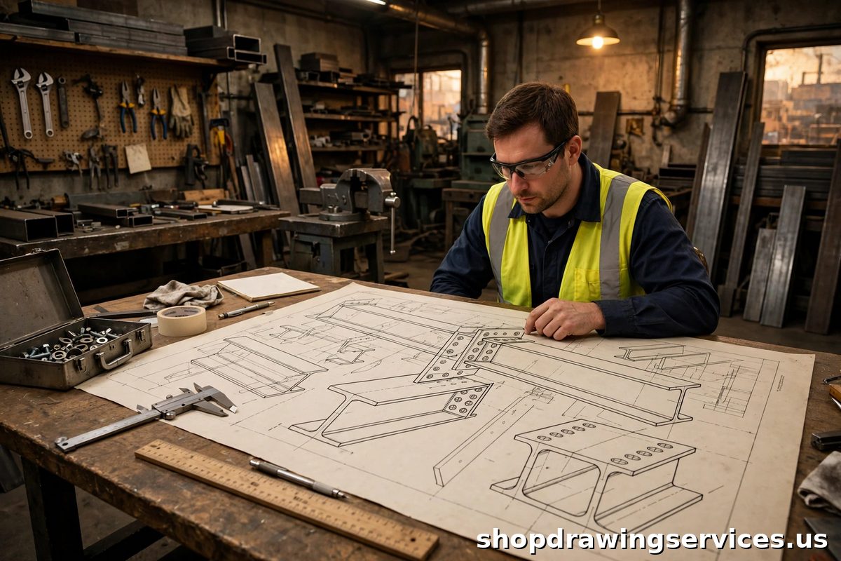
Erection drawings are field installation, or member placement, drawings prepared by the fabricator. They show the location and attachment of the individual steel shipping pieces. This is where piece marks, gridlines, and field bolt callouts live. The American Institute of Steel Construction (AISC) defines erection drawings this way in its glossary, and that definition is the one to hold onto: erection drawings place pieces.
An erection plan is a different document, prepared by the erector. It covers how the work is done: delivery access, laydown, shake-out and field assembly areas, erection sequence, crane dimensions and locations, heaviest lift and radius, critical lifts, rigging, crane paths and exclusion zones, special fastening sequences, and stability during erection (AISC Certification Standard 207-16, section 5.20). A reader who looks for crane paths on an erection drawing, or for piece marks on an erection plan, is reading the wrong sheet.
Erection bracing drawings are a third, separate set, also prepared by the erector. They show erection sequence, temporary supports, and raising, bolting, and welding requirements. They answer a different question again: what holds the frame up before the permanent bracing and deck are in place.
Keep those three apart through the whole job. This post is mainly about reading the fabricator's erection drawings, and it points to the erector's plan wherever sequence, laydown, or stability is the question. For the difference between drawing sets in general, see our guide to shop drawings vs fabrication drawings vs erection drawings.
Read in this order, every time
1. Title block and revision first
Check the sheet number, the revision, and the date, and confirm this is the approved set. Never read a superseded erection sheet because it was the first one opened, or because it was already pinned to the trailer wall. If two revisions are in circulation, stop and confirm which one governs before any piece tied to that sheet is lifted.
2. General notes and drawing index next
Read the general notes before reading any member. They state the material grades, bolt grades, welding standard, abbreviation conventions, and which sheets cover which level or zone. The drawing index tells you which sheet holds each level, zone, or detail, so you do not hunt through the set while the crane waits.
3. Gridlines and elevations
Gridlines are the frame's address system. By convention, letters run on one axis and numbers on the other, for example A through E on one axis and 1 through 5 on the other, and a column lives at a grid intersection. Grid dimensions are structural centres, not finished face dimensions, so do not set a piece off a finished wall face and expect it to land on its grid.
Elevations fix height. A plan alone cannot place a piece vertically, so read the plan together with the elevation for that line. Check that a grid label is written the same way on every sheet that references it. A label that shifted on one sheet compounds through every sheet that references it.
4. Piece marks, then orientation and sequence
Find the piece mark, confirm its grid location, then check which way the member faces, which end goes up or north, and where it sits in the erection sequence. Erection sequence is not the order steel arrived on the truck. It is the order the erector's plan sets, and it is driven by stability, access, and connection order, not by delivery convenience.
5. Connections last and slowest
Read connections after the member is placed in your mind, not before. Check field welds, field bolt patterns, plate dimensions, and the detail sheet each connection points to, and check bolt count and plate against the members they join. A flag symbol on a weld symbol means the weld is made in the field, not the shop, under the AWS A2.4 convention. Missing that flag is a classic shop versus field error: a weld planned for the shop cannot be made in the field without a revised plan, and a field weld sent to the shop arrives as an unmade joint.
Piece marks: one mark, three places, no exceptions
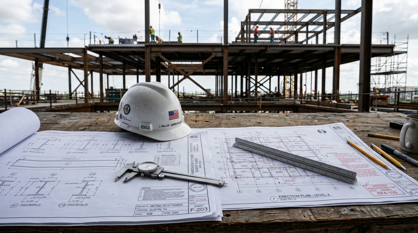
Every shipping piece carries one unique piece mark, and that mark is the thread that ties the whole set together. The mark on the erection drawing, the mark on the shop drawing, and the mark on the fabricated piece must all match. That three-way match is the single most important cross-check in this post.
A mark is not a size. The erection drawing gives location. The shop drawing and the bill of materials give size, length, grade, and holes for that mark. Do not claim a universal piece mark format: formats vary by fabricator and by project. The rule is consistency within the set, not one format for all sets.
Table 1 is a three-way trace for hypothetical pieces only. No real project marks, sizes, or sheets are used. One row deliberately shows a mismatch, because the mismatch row is the one that teaches the rule.
Erection drawing and grid | Piece mark | Shop drawing | Member size from bill of materials | Match check |
|---|---|---|---|---|
E-3, grid C-3 | B-214 (hypothetical) | S-118 (hypothetical) | W21x44 (hypothetical) | Match: erection mark equals shop mark equals piece mark. Clear to erect in sequence. |
E-3, grid C-4 | C-108 (hypothetical) | S-121 (hypothetical) | W18x35 (hypothetical) | Match: erection mark equals shop mark equals piece mark. Clear to erect in sequence. |
E-4, grid D-2 | B-219 (hypothetical) | S-126 (hypothetical) | W24x55 (hypothetical) | Mismatch: the piece in the laydown area is marked B-219, but the erection sheet at D-2 calls for B-216. Stop, quarantine the piece, send an RFI, do not erect. |
That third row is the whole point. A mismatch is not a paperwork delay to work around. It is a stop signal. Erecting the wrong piece can mean cutting it out later, reordering, and losing the sequence for every piece that was meant to follow it.
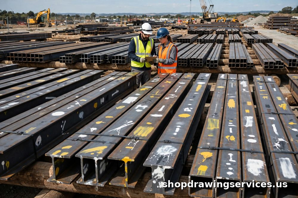
Shake-out: sorting steel before the first lift, not during it
Shake-out is sorting and laying out delivered steel by erection area and sequence before lifting begins, using the packing list and the piece marks, not by guessing from member size. Size is not identity. The mark is.
Unload near the installation zone the erection plan designates, not wherever the truck could park. A pile in the wrong place has to be moved twice, and the second move happens under crane time pressure. Sort by mark and by sequence, with bundles labelled by bundle number, mark range, area or sequence, and weight or handling note, so the crew can find a piece without restacking the pile.
Keep small parts separately. Bolts, clips, brackets, and plates belong in marked boxes or bags, listed separately and separated by area or shipment batch. Small parts are the easiest things to lose and the hardest to replace on erection day.
Marks must stay readable after coating, handling, and transport. Use painted marks plus physical tags where labels may be damaged, and check readability at shake-out, not at the moment of the lift. A piece found in the wrong laydown area is a sequence error, not a paperwork error: it means the next lift waits while the pile is restacked, or the wrong piece goes up first.
Use the checklist below before the first lift. A checklist with an empty box is still useful: it is the list of open items, and an open item found here costs minutes, while the same item found at the crane costs hours.
Unload zone confirmed against the erection plan, not chosen by truck access alone.
Bundle labels checked against the packing list: bundle number, mark range, area or sequence, weight and handling note.
Piece marks checked readable after coating, handling, and transport; tags added where labels may be damaged.
Small parts boxes listed separately by area or shipment batch, and stored where the crew can reach them without restacking steel.
Sequence order confirmed with the erector, so the first piece needed is the first piece reachable.
Quarantine area designated for any piece whose mark matches no erection drawing, or whose mark is unreadable.
Stop rule: a piece whose mark matches no erection drawing, or whose mark is unreadable, is quarantined and queried, never guessed into place. That rule protects the sequence, the connections, and the crew.
Field bolt schedules: read them, count against them, do not invent them
The field bolt schedule lists, per connection or per area, the bolt diameter, grade, type, length, and quantity the field crew needs, and which joint type applies. The joint types are snug-tight, pretensioned, or slip-critical. This post does not re-teach joint types; our guide to steel connection detailing mistakes covers them, and the schedule tells you which type each connection on this job requires.
Check, per connection: bolt count against the detail, diameter and grade against the schedule, length against the grip (the plies plus washers and nut), and lot separation, because bolts are tracked by production lot. A bolt of the right diameter and the wrong length is not close enough, and a bolt from a mixed lot is not traceable if a question comes up later.
One verifiable background rule helps the reader understand what should have arrived. AISC Code of Standard Practice, section 7.8.3, in the May 9, 2022 edition, states that where the fabricator is not the erector, the fabricator furnishes bolts, nuts, and washers in sufficient quantity for all bolted field connections, including an extra 2 percent plus three bolts, subject to a minimum of five extra bolts of each grade, type, diameter, length, and production lot number. Present that as the Code's allowance rule, not as a promise that any specific delivery contains that surplus. The crew still counts what arrived against the schedule.
Table 2 works through hypothetical arithmetic only. A connection calling for 12 bolts, counted on arrival as 10, is short by 2 before the Code allowance is even considered: 12 minus 10 equals 2 short. The allowance calculation is separate: 2 percent of 12 equals 0.24, plus 3 equals 3.24, so the allowance rule points to at least 3 extra bolts, and the 5 bolt minimum per grade, type, diameter, length, and lot governs where it applies. Count, compare, and report the shortage before the connection is needed.
Check (hypothetical example only) | Arithmetic | Result |
|---|---|---|
Bolts called for vs bolts counted on arrival | 12 minus 10 | Short by 2, before any allowance |
Code allowance on the called-for quantity | 2 percent of 12 equals 0.24, plus 3 equals 3.24 | Allowance points to at least 3 extra bolts |
Minimum extra per grade, type, diameter, length, and lot | 5 bolt minimum governs where it applies | Do not treat the 3.24 figure as the full requirement where the 5 bolt minimum applies |
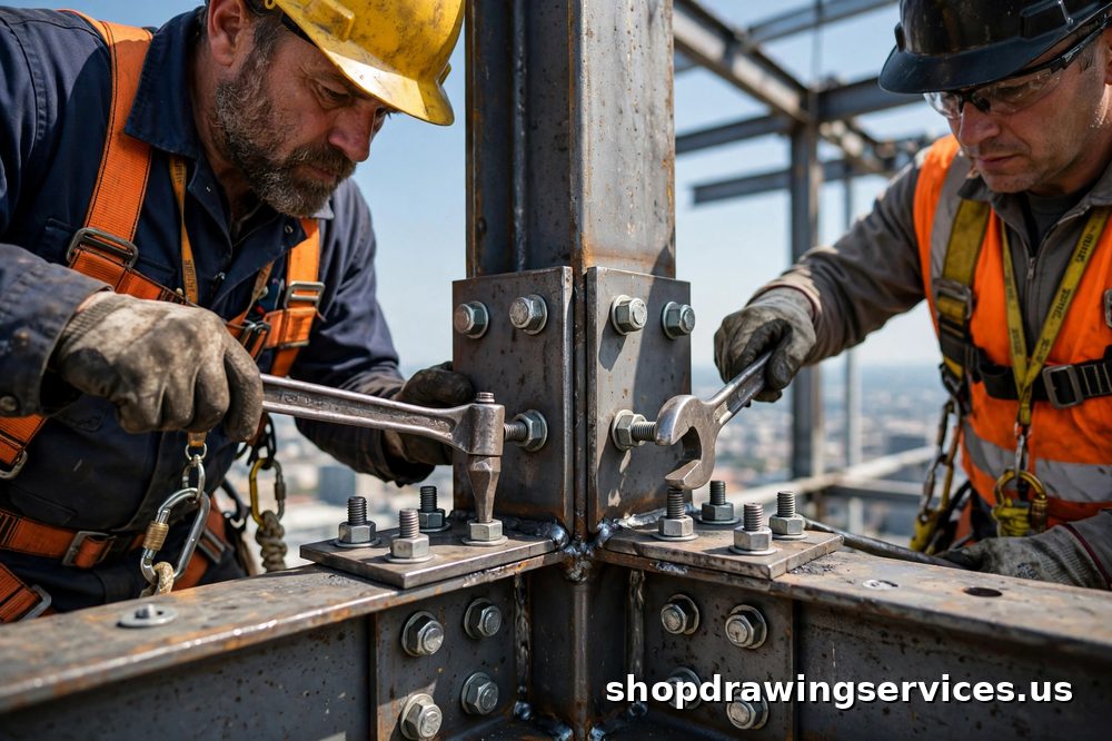
Temporary bracing and stability: what holds the frame up first
A partially erected frame is not stable on its own. Temporary bracing, guying, and the sequence in the erector's plan and erection bracing drawings hold the frame until the permanent bracing and deck are in. Read the bracing drawings before the first lift. This post reads drawings; it does not replace the erector's plan, the crane charts, or site safety procedures, and it does not give lifting, rigging, or crane capacity instructions.
The practical reading habit is simple: for each lift, confirm the piece, the grid, the connection, and the bracing that must be in place before and after that lift. If any of those four is unclear, the lift is not ready.
When to stop and ask, instead of reading on
Four findings stop the reading and start a question: a revision conflict, a piece mark mismatch or unreadable mark, a grid label that reads differently on different sheets, or a connection whose bolt count, plate, or detail reference does not agree with the members it joins. Each goes back as an RFI before the affected steel is erected, not after. Ask early, in writing, with the sheet, grid, and mark in the question.
What to send when you ask for erection drawings
Send the approved structural and architectural set, the connection design information the detailer needs, the erection sequence constraints if the erector has already set them, and the bolt and material standards that govern the job. A clean input set is what makes a clean erection set, and a clean erection set is what keeps the crane moving. If you are planning a steel package and want erection drawings that read this clearly in the field, contact our detailing team with your project scope and schedule, and we will confirm what your set needs before detailing starts.