The short answer: draw the section first, freeze the model version, and sign off zone by zone
Short answer: A tight ceiling plenum is cleared in section, not on plan. Start with the finished ceiling line at the bottom and the structure at the top, then stack every system between them at its full installed depth, including insulation, hangers, supports, and access space. Federate the current discipline models into one coordination model, freeze that model version for the round, test system pair by system pair and zone by zone in Navisworks Manage Clash Detective, classify every clash as hard, soft, or clearance and workflow, resolve gravity lines first, then large duct mains, then pressure piping and containment, then ceiling devices, and re-run the affected tests after every accepted move. No zone is released for install until its tests re-run clean on the frozen model version. A report that lists clashes without a model version, a zone, and a re-run result is a progress note, not a clearance.
Who this is for: general contractors, MEP subcontractors, BIM coordinators, architects, and engineers who prepare, review, or install coordinated MEP work in commercial buildings in the United States where ceiling height is tight and several systems share one plenum.
Our BIM coordination service prepares coordination drawings the way an installer reads them: section first, zone by zone, with the model version named on the drawing so the field crew knows exactly which version they are building from.
A tight plenum is a section problem, not a plan problem
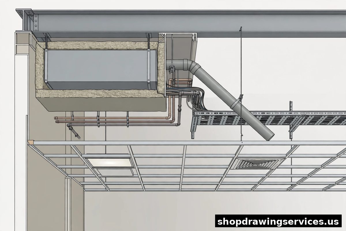
On plan, a duct, a pipe, and a cable tray can all pass through the same corridor. In section they cannot, because the beam depth, the slab soffit, the ceiling height, and the ceiling devices all take the same vertical inches. That is why the first drawing in a plenum coordination package should be a section, drawn per zone, showing the finished ceiling line, the structure above it, and every system stacked between them.
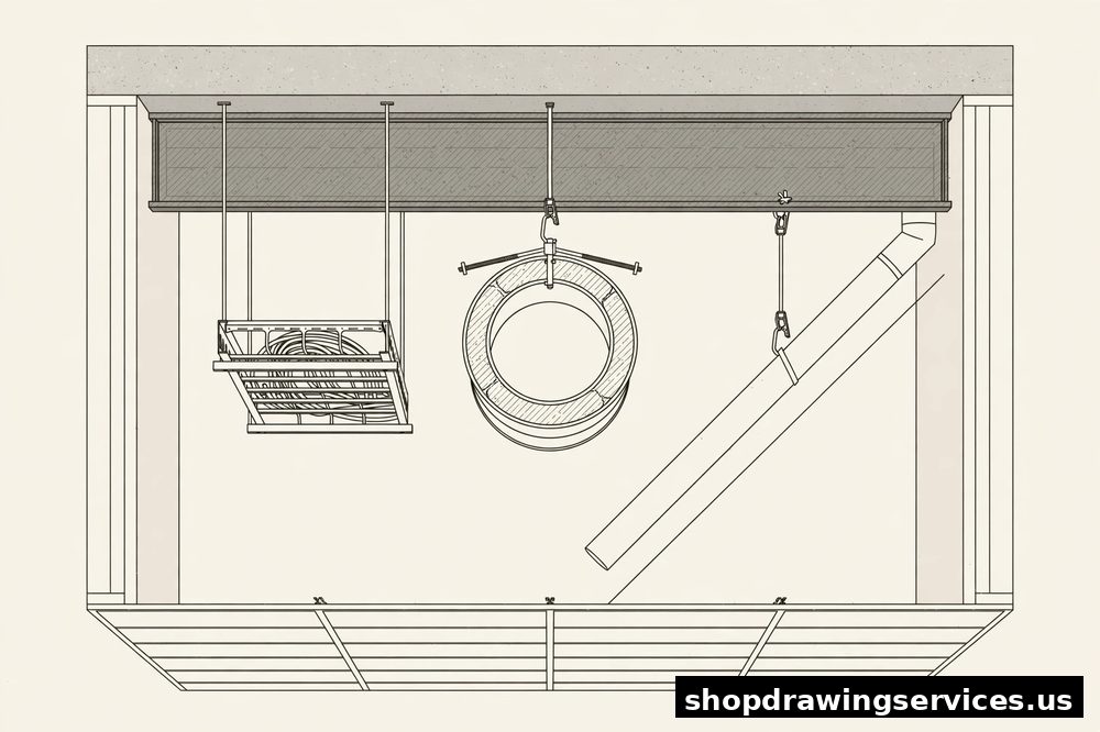
Artifact 1: plenum section excerpt (hypothetical corridor bay)
This section is hypothetical. Real dimensions come from that project's structural, mechanical, plumbing, and electrical drawings, never from a previous job.
Layer in the section, top to bottom | What it takes | Why it is drawn |
|---|---|---|
Slab soffit and beam | Full beam depth at the lowest beam in the bay | The beam, not the slab, sets the available height in that bay |
Gravity drain pipe | Pipe size plus slope over the run, set first and not jogged up over a duct | A gravity line keeps its slope, so it cannot be rerouted the way a pressure pipe can |
Large duct main | Duct size plus insulation plus hanger drop below the duct | The largest single occupant, and the one every other system must work around |
Pressure piping and sprinkler main | Pipe size plus insulation plus hanger, with valve and damper access marked | Small pipes still fail a plenum when their valves sit above a fixed ceiling with no access panel |
Cable tray and conduit | Tray width plus fill plus pull space and a separation from other systems | A tray that can be installed but not pulled or serviced is a future outage, not a clearance |
Finished ceiling line and devices | Ceiling tile plane, diffuser, light fixture, sprinkler head, and access panel positions | Devices compete for the ceiling plane and for the access above it, and must be coordinated with the section, not after it |
Hard clashes are the easy third of the job
Navisworks finds intersections, and intersections are only the start. A plenum fails just as often on two other kinds of conflict that a raw clash list can hide. Soft clashes are cases where two systems do not touch but sit close enough that neither can be installed, insulated, or serviced. A duct and a pipe with no gap between them cannot both be insulated. A tray tight against a beam cannot be pulled. Clearance and workflow clashes are cases where the geometry fits but the work does not: a valve above a fixed ceiling with no access panel, a damper that cannot be reached for testing, a diffuser landing where a light fixture already sits, a sprinkler head blocked by a duct so its spray pattern is interrupted, or a cable tray with no pull space at a bend.
The workflow must test for all three, and the report must label which kind each clash is. If it does not, the team will clear the hard list, declare the zone coordinated, and still fail in the field, because the installer will discover the soft and clearance problems with a ladder and a ceiling tile in hand. In Navisworks Manage, Clash Detective supports hard interference tests and clearance tests, with tolerance, grouping, viewpoints, and status tracking for each group. Use those tools as intended: build separate tests for hard interference and for clearance, set the tolerance per system pair as a project decision, group repeated conditions so one decision covers them, and save a viewpoint for each group so a reviewer can find the same condition again without hunting through the model.
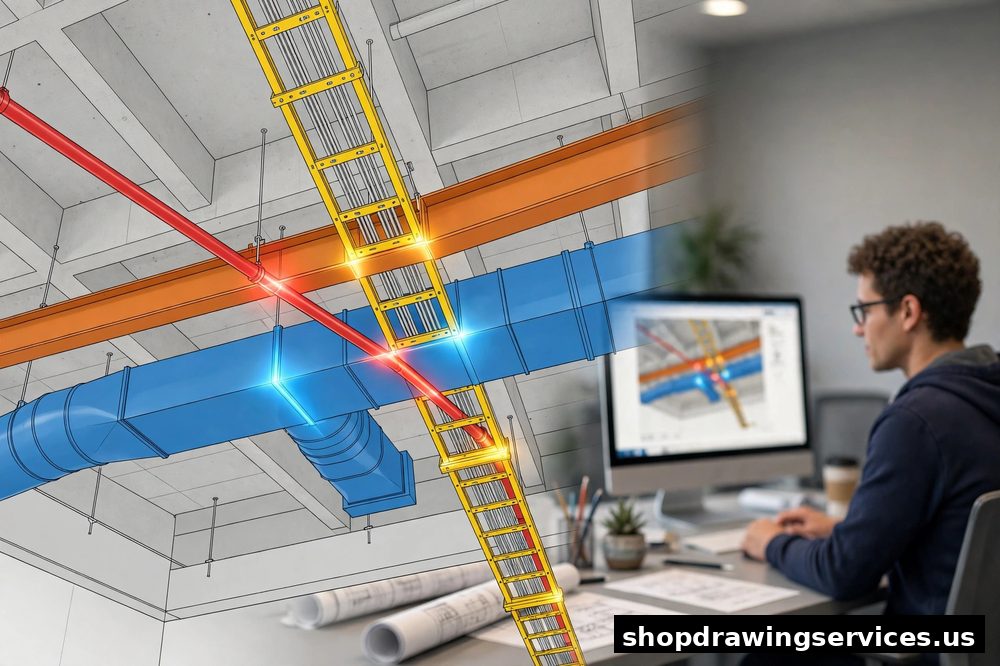
Gravity outranks everything that can be rerouted
Coordination order matters, and the order is not alphabetical and it is not first come, first served. A drain or waste pipe keeps its slope, so it cannot be jogged up over a duct the way a pressure pipe or a cable tray can. In a tight plenum, set the gravity lines first, then the large duct mains, then the remaining pressure piping, the fire main, and the electrical containment, in that order, and say so explicitly on the coordination drawing.
A coordination sequence that treats every system as equally movable will move the one system that cannot move, and the field will discover it when the drain will not drain. Slope itself is a project design value from the plumbing design, never a single universal figure borrowed from another job or another code summary. The coordination drawing should show the gravity line at its designed slope across the zone, with its low point and its connection point, so a reviewer can see that no accepted move has broken the fall. The same discipline applies to duct mains: once a main is set at its size and elevation, moving it to clear a small pipe usually creates a bigger problem downstream, at a branch, a riser, or a ceiling device. Move the smaller, more flexible system first, and record the move.
A stale federated model is worse than no model
The most common failure in plenum coordination is not a missed clash. It is a clash report run on last week's model after one trade has already rerouted. The workflow must freeze a model version per coordination round, name that version in the report, and re-run the tests after every accepted move, not just at the end of the round. An install crew working from a superseded coordination drawing is working from bad information, however clean the last report looked.
Re-running after accepted moves is the second half of the same discipline. Every accepted move changes the model, and a changed model can create a new clash where none existed before. A duct moved to clear a beam can land on a sprinkler main. A tray moved to clear a pipe can lose its pull space. The affected tests, and only the affected tests if the round is large, are re-run on the updated frozen version before the zone is signed off. A zone signed off on a report that predates its last move has not been signed off at all.
LOD 300 is not enough to coordinate, and that is a scope point
The BIMForum Level of Development Specification, which builds on the American Institute of Architects framework, defines LOD 300 as a model element represented as a specific system at accurate quantity, size, shape, location, and orientation. LOD 350 adds the parts that take space but are not the system itself: supports and connections, and the parts necessary for coordination with nearby or attached elements. For MEP coordination, that means supports and hangers, insulation, sleeves and penetrations, and maintenance access clearances are modelled, not left as notes.
A duct modelled without its insulation and hanger will clear on screen and clash in the ceiling. A pipe modelled without its support will clear on screen and clash with the tray below it. A valve modelled without its access clearance will clear on screen and fail at commissioning, when nobody can reach it. The post must require those elements as coordination inputs, and must not claim a zone is clear until they are in the federated model. That is a scope point to agree before modelling starts, because adding hangers, insulation, and access to a model that was priced at LOD 300 is rework, and rework agreed late is an argument. Agree it in the coordination procedure, per zone, before the first federated model is built.
The seven step workflow, in the order it is run
Section first: ceiling line, structure, available height, and every system's full installed depth including insulation, hangers, and access, drawn in section per zone.
Federate and freeze: current discipline models only, shared origin, version named in the report, no stale model in the run.
Build tests by pair and by level: structural versus HVAC, HVAC versus plumbing, electrical versus fire protection, and so on, per floor and per zone, not one building-wide test.
Set tolerance and grouping deliberately: tolerance tight enough to catch real conflicts, grouped so one repeated condition is one decision, not fifty identical clashes.
Classify every clash: hard, soft, or clearance and workflow, with an owner trade and a viewpoint saved in Navisworks Manage Clash Detective for each group.
Resolve in priority order: gravity lines, then large mains, then pressure piping and containment, then ceiling devices, with each accepted move recorded and the affected tests re-run before sign-off.
Sign off zone by zone: no zone is released for install until its tests re-run clean on the frozen model version, and the sign-off names the model version, the zone, and the date.
Our HVAC mechanical detailing and plumbing and fire protection detailing feed this workflow as ceiling occupants with their own sizes, slopes, and access needs, not as lines on a plan. Duct fabrication detail and sprinkler head layout rules belong to their own later guides, and this post keeps them at the level of ceiling occupants competing for the same height.
Artifact 2: clash log excerpt (hypothetical zone, three clash kinds)
This log is hypothetical. Real clash logs name the project model version, the floor and zone, and the trade owner for each group.
Clash (hypothetical) | Kind | Pair and level | Owner | Resolution |
|---|---|---|---|---|
Duct main passes through a steel beam web opening that is smaller than the duct plus insulation | Hard | Structural versus HVAC, level 2, corridor zone B | Mechanical, with structural review | Duct rerouted below the beam in that bay, section redrawn, affected tests re-run |
Pipe insulation touches cable tray side, leaving no gap to install or service either system | Soft | Plumbing versus electrical, level 2, corridor zone B | Plumbing, with electrical review | Pipe offset by the insulation thickness plus working gap, tray position unchanged, tests re-run |
Isolation valve sits above a fixed ceiling panel with no access panel, and a diffuser lands where a light fixture is already set | Clearance and workflow | Plumbing and ceiling devices versus architecture, level 2, corridor zone B | Plumbing and architecture, jointly | Access panel added on the reflected ceiling plan, diffuser moved one tile, ceiling plan and section reissued, tests re-run |
Ceiling devices are systems too
Lights, diffusers, speakers, sprinkler heads, smoke detectors, and access panels all compete for the ceiling plane and for the plenum access above it. Coordinate them on the reflected ceiling plan against the plenum section, not after the MEP routing is frozen. A diffuser moved by one tile to clear a beam is a coordination change, and it needs the same re-run as a duct move, because it can land on a light, a sprinkler head, or an access panel that was already placed.
Artifact 3: zone sign-off checklist, before install is released
Model version: federated model version and date named on the report and on the coordination drawing, and they match.
Tests run: tests listed by system pair, floor, and zone, with tolerance and grouping recorded for each test.
Clashes cleared: every clash group classified as hard, soft, or clearance and workflow, with an owner trade, a viewpoint, and a recorded resolution.
Re-run result: affected tests re-run clean on the frozen model version after the last accepted move, not on an earlier version.
Ceiling device check: reflected ceiling plan checked against the plenum section for that zone, including access panels above valves, dampers, and junction boxes.
Release: zone, model version, and date signed by the coordinator, with the drawing version issued to the field named on the sign-off.
A zone missing any one of these lines is not released. A partial sign-off, with a known clash left for the field to solve, is a field problem with a signature on it.
What to send, so a zone gets cleared the first time
Send the section per zone, with ceiling line, structure, and every system's full installed depth. Send the federated model version and date, with the discipline models and their dates listed. Send the clash report with tests by pair and level, tolerance and grouping recorded, every clash classified, owned, and viewpointed, and the re-run result after the last accepted move. Send the reflected ceiling plan for the zone, with access panels marked. Send questions early: where the beam depth is unclear, where a gravity slope cannot be held at the ceiling height given, where a ceiling device has no access, and where the model is missing hangers, insulation, or sleeves, ask before install, not after the ceiling is closed.
If your next project has a tight plenum and the section, the model version, or the zone sign-off is still open, send the drawings and the coordination procedure before install starts. Our team will check the set against the seven steps above, mark what is ready, and list what still needs a project value. Start with our contact page and tell us the floor, the zone, the finished ceiling height, and the lowest beam in the bay. Those four facts decide most of the coordination that follows. See our quality assurance process, covering the two stage review every set goes through before it leaves the office, and our shop drawing services hub for the full trade list.