Steel Erection Drawing Services for Contractors & Fabricators
Clear, clash-free steel erection framing plans, gridded elevations, anchor bolt setting templates, and field-bolted connection references. Built to keep crane picks safe, ironworkers productive, and structural jobsite assemblies aligned to AISC 303-22 standards.
Build It Right in the Field: Precision Steel Erection Plans
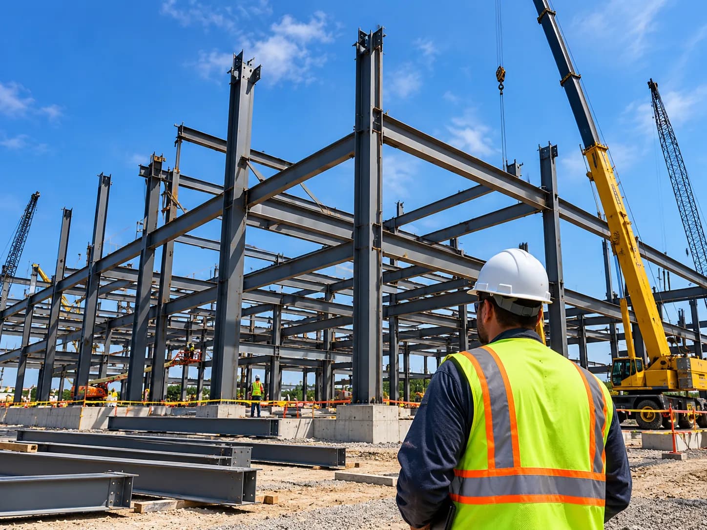
When structural steel arrives on an active commercial jobsite, every minute of crane rental time counts. Crane operators, rigging foremen, and field ironworkers cannot pause hoisting operations to decipher vague architectural drawings or search through single-part fabrication sheets. While structural steel shop drawings satisfy design-intent approvals, field crews need clear, authoritative Steel Erection Framing Plans (E-sheets) that show exactly where every beam, column, brace, and lintel belongs.
Our steel erection drawing packages translate approved structural designs and 3D Tekla/SDS2 models into intuitive, field-ready documents. We clearly identify column building grids, piece mark identifiers, top-of-steel (TOS) elevations, field bolt callouts, match-mark conventions, and anchor rod patterns. By establishing direct alignment between the fabricator's shop tags and the field erection layout, our drawings prevent costly field misfits, rework, and site delays.
Every member features an unambiguous mark corresponding directly to the fabricator's shipping tags.
Explicit coordinate dimensions and top-of-steel elevations keep floor and roof framing level.
Fastener diameters, ASTM grades, and AWS D1.1 weld symbols eliminate on-site guesswork.
Detailing conforms strictly to Section 7 erection tolerances, plumbness guidelines, and fit-up allowances.
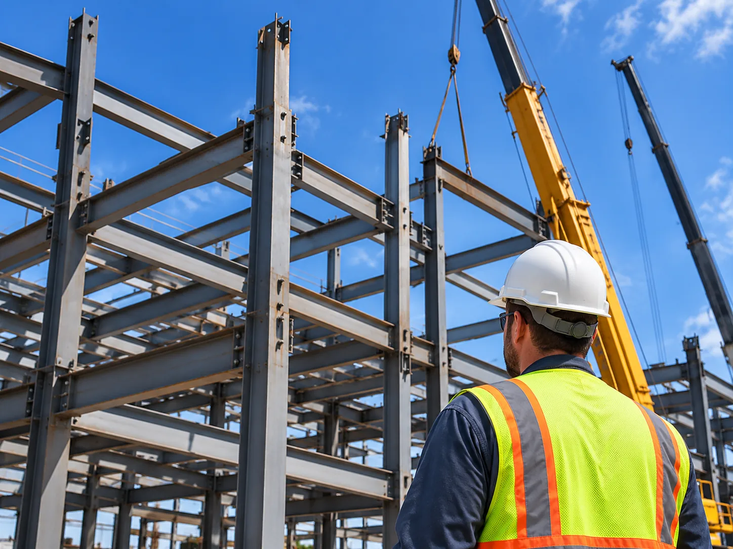
Field Structural Framing Plan
Grid Lines, Piece Marks & Elevation Levels
What Steel Erection Drawings Include
Every drawing in our erection package is engineered for readability under active field conditions. We ensure all critical member marks, connections, and datum references are clearly annotated and cross-referenced.
Framing Layouts & Vertical Elevations
- Complete Plan Views (E-Sheets): Detailed layouts for foundation anchor bolts, ground floor framing, elevated floors, mezzanine platforms, roof framing, and penthouse structures.
- Gridded Erection Elevations: Full vertical sections along major building column lines showing tier splices, vertical bracing bents, floor heights, and finished floor elevations.
- Member Orientation Callouts: Explicit North arrows, column flange orientations, and asymmetrical beam mark orientations preventing 180-degree reversed member installation.
- Top-of-Steel (TOS) Ordinates: Clear callouts for standard floor elevations, roof slopes, drainage valley drops, slab recesses, and stepped beam headers.
Connections, Fasteners & Field Details
- Field Connection Detail Bubbles: Cross-referenced section bubbles indexing specific bolted shear tabs, moment connections, bracing gussets, and column base plates.
- Fastener Specifications & Bolt Lists: Itemized field bolt summaries listing required ASTM bolt diameters (A325, A490, F3125), lengths, washer types, and hole clearances.
- AWS Field Welding Symbols: Distinct weld symbols specifying field-applied fillet and groove welds, complete with joint preparation details and backing bar specifications.
- Revision Cloud Tracking: Prominent revision triangles (▲1, ▲2) and revision clouds highlighting design modifications between contract drawing submittal releases.
Key Deliverables in Every Erection Package
We deliver fully coordinated, professional drawing sets formatted for standard commercial sheet sizes (Arch D / Arch E1) and accessible PDF tablets on site.
Erection Framing Plans (E-Sheets)
Complete 2D floor and roof framing layouts keyed to building grids. Displays exact piece marks, member orientations, top-of-steel (TOS) elevations, step changes, slab openings, and cross-references to connection details.
Steel Erection Elevations & Wall Sections
Vertical framing views illustrating column splice lines, multi-tier elevations, vertical bracing geometries, wall girts, and lintels. Ensures erectors understand vertical clearances and work-point locations.
Field Connection Callout References
Clear visual callouts identifying field-bolted and field-welded connections. Distinguishes shop vs field scope, specifies fastener grades (A325/A490/F3125), bolt lengths, hole types, and AWS D1.1 weld symbols.
Anchor Bolt Placement & Setting Plans
Foundation coordination drawings showing anchor rod cluster layouts, centerline offsets from column grids, rod diameters, projection lengths, base plate sizes, and grout thickness allowances.
Erection Sequencing Reference Plans
Optional coordination drawings showing agreed erection zones, phases, and member cluster grouping. Communicates planned staging interfaces established by the erector or general contractor.
3D Isometric & Coordination Views
Exported 3D isometric perspectives and framing assembly overviews from Tekla/SDS2 models. Helps site foremen, crane operators, and rigging teams rapidly visualize complex multi-tier connections.
Erection Sequence: From Initial Columns to Complete Frame
Successful structural steel erection depends on systematic assembly logic. The visual progression below illustrates typical conceptual framing development from base anchors to full multi-story frame lock-in.
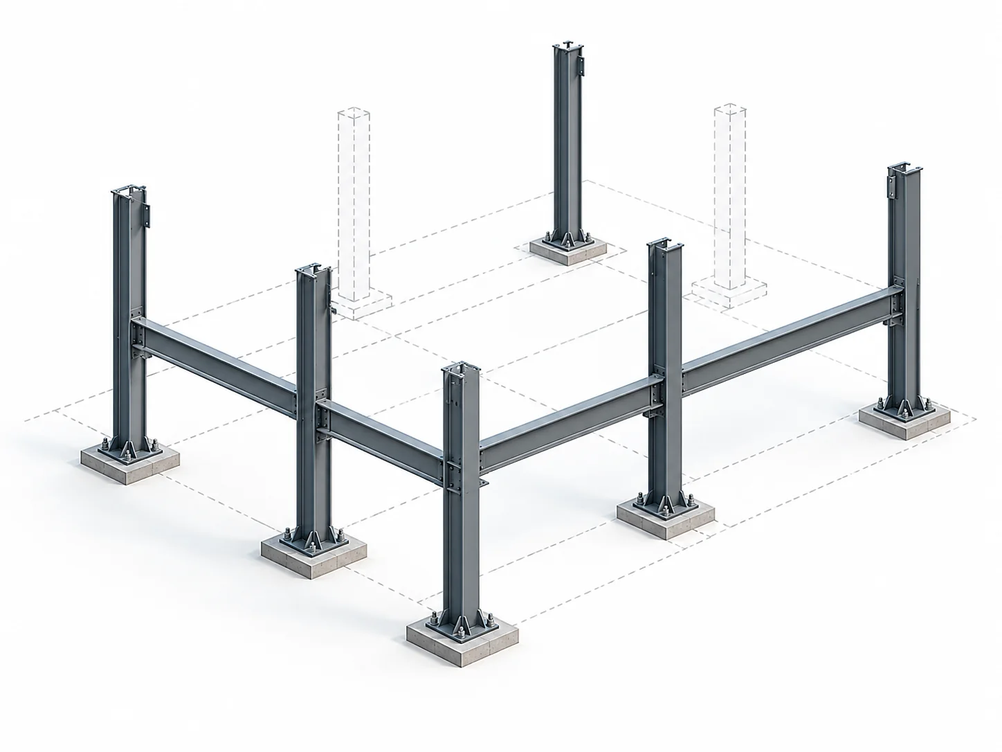
Initial Columns & Anchor Setting
First tier columns are set onto verified foundation anchor rods using leveling nuts. Initial bays are cross-braced to establish the primary stability core required before releasing crane lines.
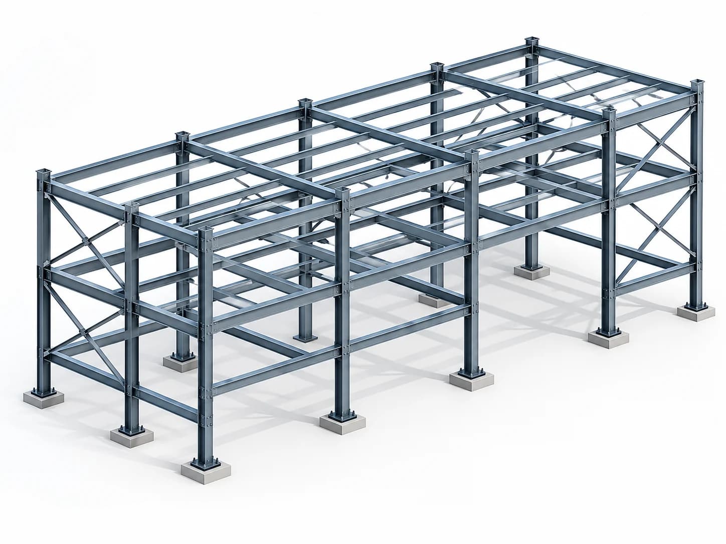
Intermediate Framing & Plumb-Up
Main floor girders and infill beams are hung between columns. Survey crews verify column plumbness against AISC 303 Section 7 tolerances before final bolt pretensioning and field welding.
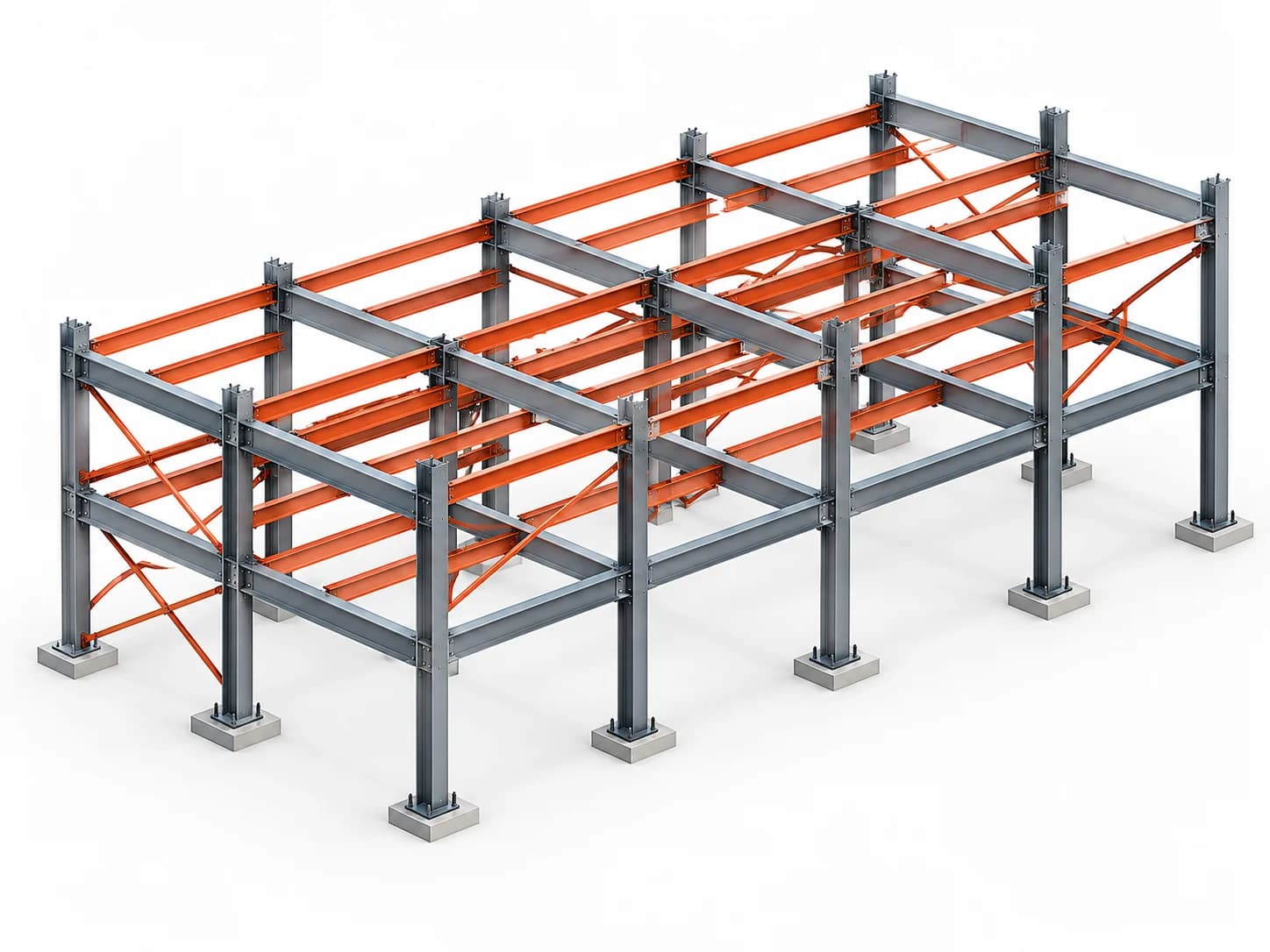
Completed 3D Structural Frame
Roof framing, penthouse trusses, and perimeter decking edge angles are secured. The fully tied framework provides structural integrity ready for metal deck installation and concrete slab pours.
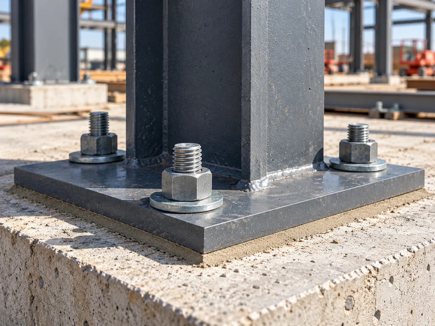
Anchor Bolt & Base Plate Coordination
The connection between the concrete foundation and the structural steel column is the most critical tolerance interface on any building project. Misplaced anchor rods, incorrect projections, or misoriented base plates result in expensive field torching or engineering delays.
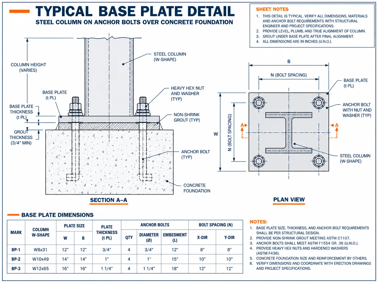
Our Anchor Bolt Setting Plans (AB-sheets) establish rigorous coordinate control dimensioned directly from the project's architectural and structural grid baselines. We provide the concrete contractor with exact center-to-center rod spacings, cluster centerlines, template patterns, projection heights above foundation, leveling nut elevations, and non-shrink grout pad clearances.
AISC Design Guide 1 Hole Sizing
Base plates are detailed with standardized oversized holes allowing up to 1/2" of field adjustment, paired with heavy plate washers to transfer axial and shear loads safely.
Grid-Referenced Dimensioning
Every anchor bolt cluster is tied back to primary grid intersections, allowing field surveyors to verify embed locations before the concrete foundation pour takes place.
Field Discrepancy Communication
If concrete field surveys reveal out-of-tolerance anchor rods, our team coordinates with the structural Engineer of Record (EOR) to evaluate approved remedial details before column delivery.
Crane & Lift Coordination Information
Modern high-production steel erection relies on synchronized communication between the crane operator on the ground and the ironworkers connecting steel at height. While steel erection drawings do not replace a licensed lift engineer, they provide vital data needed to coordinate picks efficiently.
When requested as part of the project scope, our erection drawings clearly display itemized assembly weights (lbs/tons), approximate centers of gravity on asymmetrical trusses, and designated lift point orientation marks. This allows site superintendents and rigging foremen to verify crane chart capacities, select appropriate sling lengths, and stage steel trailers in exact erection order.
Clear Boundary of Responsibility
Our services provide drafting coordination data extracted directly from the 3D model. We do NOT provide certified lift plans, crane outrigger foundation engineering, sling selection, or jobsite rigging safety oversight. Those tasks require licensed professional engineers and certified crane safety specialists contracted directly by the erector or general contractor.
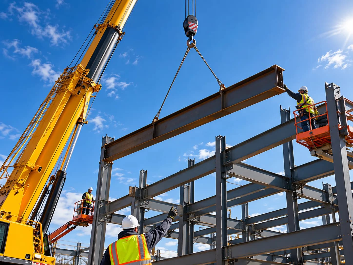
Active Crane Pick Coordination
Piece Mark Tracking & Member Weights
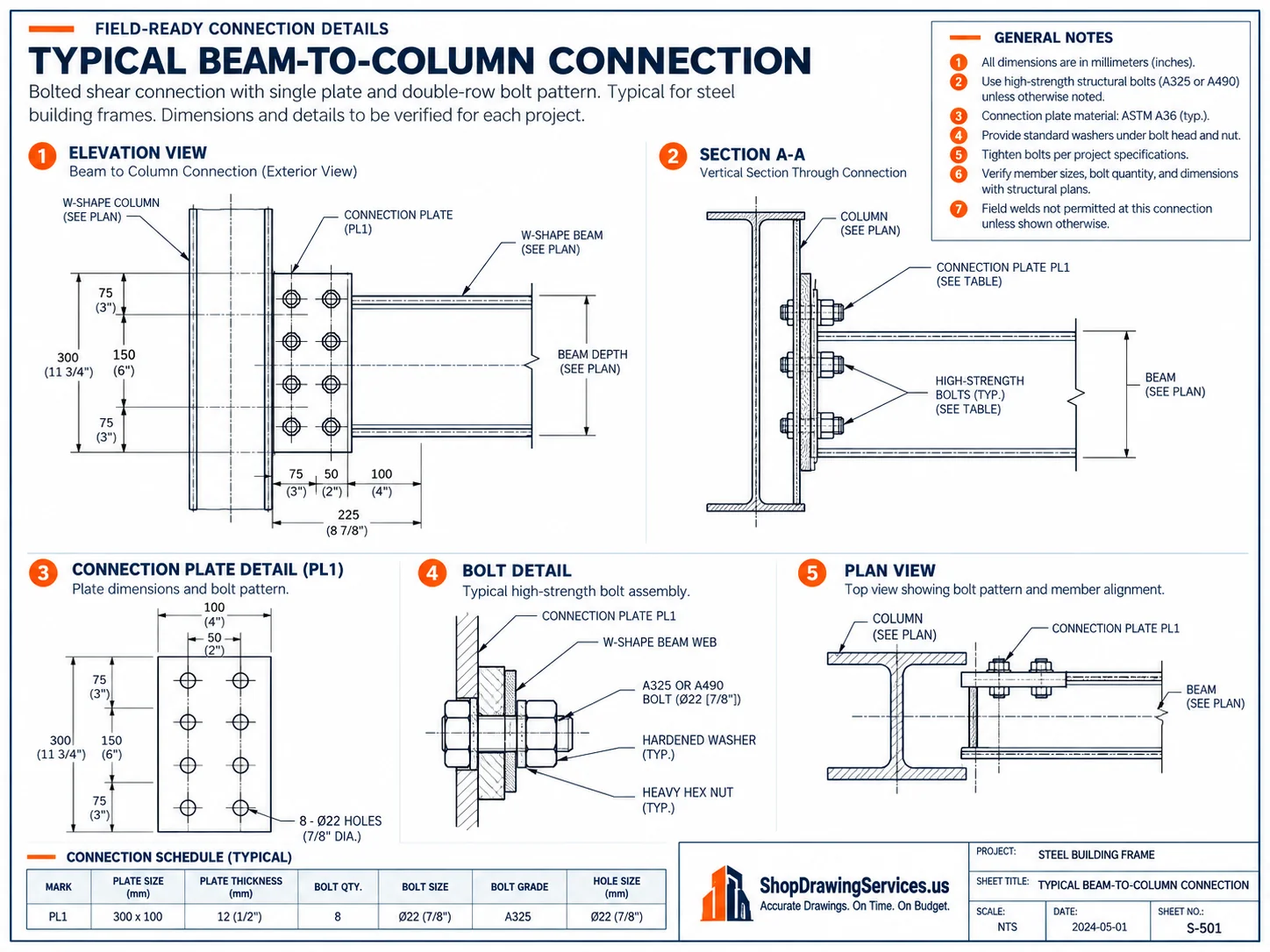
Bolted Field Connection Detail
A325 / F3125 Bolts & AWS Weld Symbols
Field-Ready Connection References
Ambiguity at connection nodes causes the majority of field rework. When ironworkers aloft cannot clearly identify whether a joint requires snug-tightened bolts or pretensioned high-strength fasteners, job progress grinds to a halt.
Our steel erection packages provide dedicated detail callout sheets indexed directly from framing plan section bubbles. We explicitly distinguish between shop-applied welds and site-applied field welds, provide match-marking conventions for asymmetrical braces, and call out standard wrench clearances to ensure pneumatic torque tools fit into connection pockets.
Clear callouts distinguish snug-tightened shear connections from pretensioned slip-critical moment joints.
Hole cluster layouts are checked against AISC Table 7-15 to ensure impact sockets clear beam flanges.
Multi-piece trusses and continuous crane girders carry stamped match-marks ensuring identical field orientation.
Standardized field weld flags, bevel preparations, and backing bar requirements clearly indicated on every joint.
Steel Erection Drawing Sample Gallery
Explore high-resolution technical sheets from our structural steel erection packages. Click any sheet to open the interactive full-screen inspection lightbox.
General Arrangement Erection Framing Plan
Comprehensive plan view displaying building grid lines, column centerlines, main framing girders, infill floor beams, joist seats, and unique erection piece marks keyed to shop fabrication assemblies.
Key Technical Data Featured:
- Alphanumeric grid system coordinated with architectural and structural foundation drawings
- Explicit member piece marks (e.g., B101, G102, C1) matching shop assembly tags
- Directional member orientation callouts (compass or grid-referenced north marks)
- Top-of-steel (TOS) elevations, step changes, slab recess locations, and opening headers
5-Step Erection Detailing & Release Process
From contract design document intake to the final stamped submittal release, our detailing process maintains rigorous quality gates at every phase.
Document Intake & 3D Model Setup
We audit structural/architectural drawings, verify grid coordinates, resolve initial discrepancies, and initialize the BIM model in Tekla/SDS2.
Output: RFI Log & Grid Model
Anchor Bolt & Embed Release
Anchor bolt setting plans are expedited to concrete contractors, detailing cluster dimensions, projection lengths, and grout thickness allowances.
Output: AB Setting Plans
Framing & Elevation Drafting
We generate floor and roof framing plans (E-sheets), vertical elevations, member piece marks, and cross-referenced connection detail callouts.
Output: Draft E-Package PDF
Design Review & EOR Coordination
Drawings are submitted to the General Contractor and Engineer of Record (EOR). Any design comments or markups are promptly resolved.
Output: Backchecked Submittal
Final Release & Revision Tracking
Final field-ready drawing sets are published with field bolt summaries, 3D views, and cloud revision tracking for ongoing site changes.
Output: Field-Ready E-Set
Required Inputs to Begin Erection Detailing
To ensure our team delivers an accurate, clash-free drawing package on schedule, please review the required design documentation checklist below.
| Input Document / File | Status | Purpose & Technical Role |
|---|---|---|
| Structural Design Drawings (S-Sheets) | Mandatory | General notes, member sizing schedules, design reaction loads, moment connection requirements, and bracing layouts. |
| Architectural Drawings (A-Sheets) | Mandatory | Grid line dimensions, exterior facade wall lines, floor-to-floor heights, roof slopes, and slab depression locations. |
| Foundation & Anchor Rod Details | Mandatory | Concrete foundation plans, column pier locations, anchor bolt diameters, embed depths, and grout allowances. |
| Current Project Addenda & RFI Logs | Mandatory | All formal design bulletins, addenda, and answered RFIs modifying framing geometry or member schedules. |
| 3D Revit / IFC Design Models | Recommended | Speeds initial Tekla/SDS2 model setup and accelerates complex multi-member clash verification. |
| Erection Sequence & Zoning Requirements | Conditional | Required when the project mandates phased erection releases, specific crane access corridors, or tiered member grouping. |
Scope Inclusions vs Site Exclusions
In accordance with American steel construction standards, we maintain clear contractual delineation between professional detailing drafting deliverables and site-specific erection engineering.
| Scope Category & Description | In Standard Package? | Contractual Clarification |
|---|---|---|
Building Grid & Framing Plan Layouts (E-Sheets) Core Drafting Deliverable | Included | Full gridded floor, mezzanine, and roof framing plans detailing member piece marks and TOS elevations. |
Marked Erection Elevations & Framing Sections Core Drafting Deliverable | Included | Vertical framing sheets showing column splices, bracing work points, floor heights, and connection callouts. |
Anchor Bolt Placement & Foundation Coordination Plans Core Drafting Deliverable | Included | Anchor rod cluster templates, grid offsets, rod diameters, base plate orientations, and grout allowances. |
Field Fastener Schedules & Summary Bolt Lists Core Drafting Deliverable | Included | Itemized field bolt lists by diameter, length, ASTM grade, and washer requirements per framing connection. |
3D Isometric Overview & Complex Area Snapshots Core Drafting Deliverable | Included | Perspective 3D model exports illustrating intricate multi-member nodal connections for field clarity. |
Engineered Lift Plans, Crane Sizing & Crane Positioning Site-Specific Engineering (Excluded) | Excluded | Crane selection, ground bearing analysis, outrigger matting, and pick plans are the sole responsibility of the erector. |
Temporary Bracing, Guy Wire & Wind Stability Engineering Site-Specific Engineering (Excluded) | Excluded | Temporary stability analysis during erection must be engineered by a qualified specialist contracted by the erector. |
Rigging Hardware Design, Sling Angles & Shackle Selection Site-Specific Engineering (Excluded) | Excluded | Means and methods of rigging, hoisting, and tag line management belong exclusively to the certified rigging crew. |
Jobsite OSHA Safety Oversight & Controlling Contractor Duty Jobsite Operations (Excluded) | Excluded | OSHA 1926 Subpart R compliance, site safety plans, and fall protection enforcement are managed on-site. |
As-Built Field Surveying & Foundation Deviation Redesign Field Operations (Excluded) | Excluded | Field surveying of misplaced anchor bolts and licensed remedial design modifications require EOR authorization. |
Governing Codes & Industry Standards
Our steel erection drawing packages strictly reflect American industry specifications governing structural steel design, fabrication tolerances, bolting criteria, and field safety.
Code of Standard Practice
Sections 4 & 7 govern approval documents, field plumbness, piece mark conventions, and erection fit-up tolerances.
Subpart R Steel Erection
Drawings support erector compliance with column anchor bolt stability (4 bolts minimum) and perimeter fall protection line supports.
High-Strength Bolting
Fastener designations comply with ASTM F3125 (Grade A325/A490) snug-tightened and pretensioned connection rules.
Structural Welding Code
Standardized welding symbols unambiguously communicate joint preparations, fillet sizes, and field weld flags across all details.
Who We Work With Across the US Market
We provide tailored steel erection documentation for construction professionals managing commercial, industrial, institutional, and mixed-use structures nationwide.
Steel Erectors & Riggers
We supply ironworkers and field crews with high-legibility framing plans developed through our comprehensive structural steel detailing workflow, explicit connection details, bolt schedules, and 3D views that eliminate hoisting confusion and maximize hook time.
Structural Steel Fabricators
Our erection plans link seamlessly to shop fabrication assembly drawings, piece mark tags, shipping manifests, and CNC production files generated in the same Tekla/SDS2 model.
General Contractors & PMs
We support commercial general contractors and construction managers with advance anchor bolt setting plans, multi-trade slab clearance coordination, and phased submittal releases that protect overall milestone dates.
Facility Types & Structural Typologies Supported:
Cost & Timeline Factors for Erection Packages
Drawing package pricing and drafting schedules depend on factual project parameters. Understanding these drivers ensures transparent bidding without surprise surcharges.
Total Tonnage & Piece Count
A repetitive 500-ton warehouse framing package requires substantially fewer detail sheets than a 150-ton multi-story building with hundreds of unique member pieces.
Framing Complexity & Geometry
Sloped roofs, skewed framing grids, radius canopies, and moment-resisting lateral frames necessitate more section cuts, elevations, and connection details.
Contract Document Completeness
Clean, 100% issued-for-construction (IFC) structural sheets with clear connection criteria accelerate detailing compared to incomplete design-development sets.
Sequencing & Phased Releases
Projects requiring fast-track anchor bolt submittals or staged multi-zone erection releases are structured around your specific site schedule milestones.
Frequently Asked Questions About Steel Erection Drawings
Find detailed answers to common technical, contractual, and operational questions regarding steel erection plans, anchor bolt coordination, and field deliverables.
Equip Your Ironworkers with Clash-Free Erection Plans
Submit your structural and architectural plans today. We review your scope, verify anchor bolt and framing requirements, and return an itemized commercial proposal within 24 hours.