

Steel Connection Detailing Services for Fabricators
Structural steel connections bring beams, columns, braces, and foundations together. Our steel connection detailing service prepares clear, project-specific shop drawing information for approved shear, moment, bracing, splice, base plate, and other connection arrangements. We coordinate connection details with structural design documents, fabricator requirements, and the applicable review process so project teams have a more organized drawing package before fabrication.
Definition & Scope
What Is Steel Connection Detailing?
Steel connection detailing documents the member interfaces and approved connection geometry needed to prepare coordinated shop and field drawings. It translates the project's structural connection requirements into drawings showing connected members, relevant plates and stiffeners, bolt patterns, weld references, connection orientation, and the relationship between shop work and field work.
Different connections need different information. A simple beam shear tab generally calls for a different arrangement and review than a welded moment connection or a braced-frame gusset. A column base depends on a foundation interface and anchor layout. Splice details depend on the actual member arrangement and approved connection design.
A useful drawing package identifies how the connection relates to the contract documents and where information is still missing. It should not quietly substitute guessed bolt sizes, welds, edge distances or connection capacities for structural engineering decisions.
Steel connection detailing is not automatically the same as structural connection design. Detailing records and coordinates approved requirements. Connection design evaluates the loads and resistance of the joint and belongs to the engineer responsible under the project's contract, including a properly appointed delegated-design engineer where applicable.
Connections are detailed from project-approved criteria. Any unresolved design requirement is sent back for clarification before release.
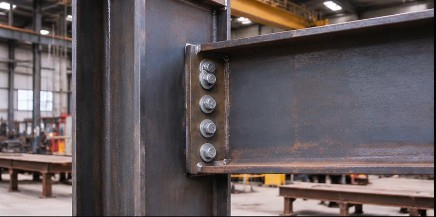
Single-Plate Shear Connection Interface
Coordinating shop welds, bolt gages, and erection clearances.
Connection Assemblies & Applications
Connection Types We Document
Connection geometry varies with the framing system, design intent and site conditions. The following are common connection categories that may be included in a steel detailing scope. The finalized scope and engineering responsibility come from the contract documents.
Shear Tab Connections
Single-plate shear connection details between supported beams and primary steel members. Drawings may identify the plate position, supported-beam orientation, approved bolt group, shop weld reference and field attachment location.
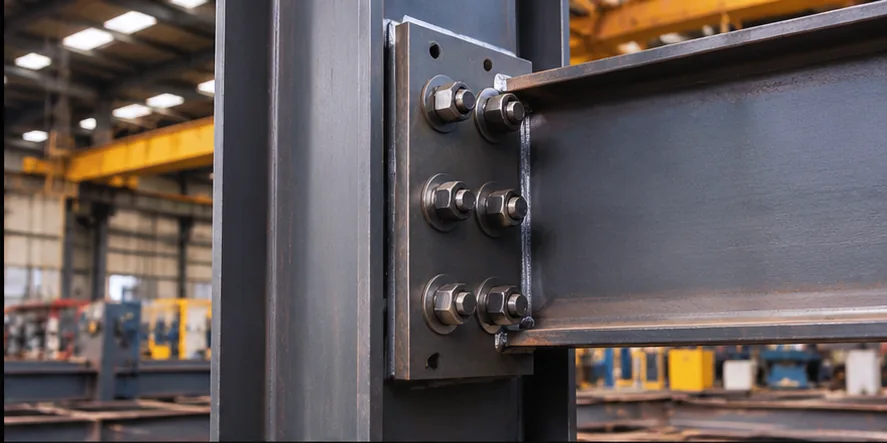
Moment End-Plate and Flange Connections
Beam-to-column or beam-to-beam moment connection arrangements that require close coordination of flange interfaces, stiffeners, plates and bolts or welds. The responsible engineer must provide or approve the design-specific information.
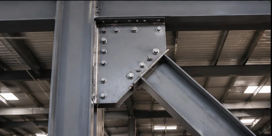
Bracing and Gusset Plate Connections
Gusset plate and brace-interface drawings for concentrically or otherwise braced steel framing. Relevant views may show work-point relationships, brace orientation, plate outline and approved attachment details.
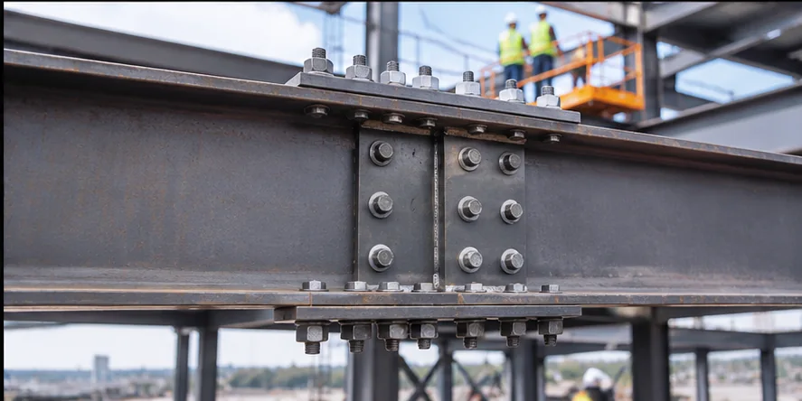
Beam Splice Connections
Connection details between separate steel beam segments, including splice plate configurations, associated fasteners and assembly references. Field versus shop installation requirements must be defined.
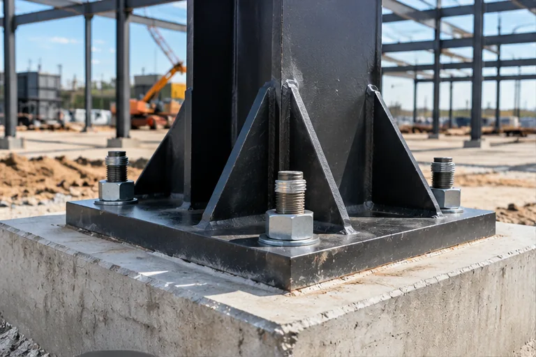
Column Base Plates and Anchor Rod Interfaces
Base plate and column-base drawing information, including supporting geometry, plate arrangements, anchor reference locations and interface dimensions drawn from the approved foundation and structural documents.
Welded and Specialty Connections
Project-specific HSS joints, welded attachments, clip angles, stiffeners and other specialty details documented to approved design information and fabrication requirements.
Illustrative photography assets. Not completed customer projects.
Deliverables Matrix
What a Complete Connection Drawing Package May Include
A connection-detailing package should help a fabricator and reviewer locate the right information without searching through unrelated views. Exact deliverables depend on the contracted scope, drawing system and approved design responsibilities.
Connection Plans and Elevations
Connected-member references, placement, elevations and orientation relative to structural grids or other approved references.
Enlarged Connection Details
Plates, angles, stiffeners, gussets, member interfaces, and approved attachment configurations clearly illustrated at readable scales.
Bolt and Hole Information
Approved fastener sizes, grades, arrangement, hole requirements (standard, oversized, slotted) and related references provided by design.
Weld References
Approved shop and field weld information, precise weld locations, AWS symbols, and associated referenced design details.
Assembly and Part Identification
Connection marks, related member or part references, and cross-references to assembly and single-part fabrication sheets.
Material or Bolt Schedules
Component lists, drawing-linked bolt schedules, plate grades, and organized hardware outputs when included in agreed scope.
Review and Revision Records
Drawing issue status, delta revision tags, clarification responses, and coordinated tracking of approved design updates.
Optional Digital Outputs
Native CAD files, 3D model extracts, CNC/DSTV data, or DXF plate profiles provided only when requested and supported by scope.
Simple Shear Framing
Shear Connection Details: Tabs and Clip Angles
Single-plate shear tabs and clip-angle arrangements are often used to connect steel beams to supporting members. The drawing must relate the supported beam's orientation to the supporting member, identify the specified connection arrangement and distinguish shop fabrication from field bolting where applicable.
A connection sheet may include the tab or angle arrangement, bolt-group reference, hole information, plate positioning, member identifiers and approved weld details. Framing geometry and beam copes may also affect fit-up. Where a connection interferes with an adjacent plate, flange, brace or other member, the conflict should be identified rather than hidden in a typical detail.
Drawing Review Checklist:
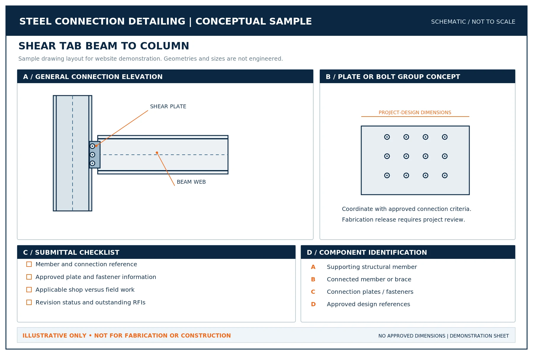
Sample Sheet C-101: Shear Tab Layout
Illustrative technical drawing sample. Not for construction.
Moment End-Plate Assembly
Tension-flange bolted geometry coordinated with column continuity plates.
Rotational Restraint & Rigid Framing
Moment Connections and End-Plate Details
Moment connections commonly require more coordination than a simple shear attachment because their geometry may involve beam flanges, columns, stiffeners, end plates, continuity-related components and specific welded or bolted interfaces.
Connection documentation should reflect the actual engineered system rather than applying one generic plate detail to every joint. Relevant drawings may show member orientation, plate geometry, stiffener positioning, flange connection references, weld symbols, approved bolt arrangements and assembly identifiers. Where the project involves a seismic force-resisting system or specially qualified connections, the required design and detailing criteria must be obtained from the responsible project documents.
Do not guess continuity plates, panel-zone reinforcement, weld size, bolt pretension category or moment strength based on a visual example. Raise missing design requirements before releasing drawings.
Lateral Force-Resisting Systems
Bracing Gussets, Work Points and Field Fit
Bracing connections link diagonal members to beams, columns and other parts of a steel frame. Their drawings need to communicate the geometry between the bracing member, gusset plate and connected structural members. Small changes in member location or work points can change the physical arrangement.
The source documents should establish the applicable connection design requirements. Detailing should show approved gusset arrangement, brace orientation, plate interfaces, relevant part marks and the distinction between shop and field attachments. On crowded framing intersections, three-dimensional coordination may help identify interferences before the fabricator cuts material.
Where the brace-to-gusset or gusset-to-frame design is not specified, the engineer responsible for that connection must resolve the criteria before a fabrication-level detail is finalized.
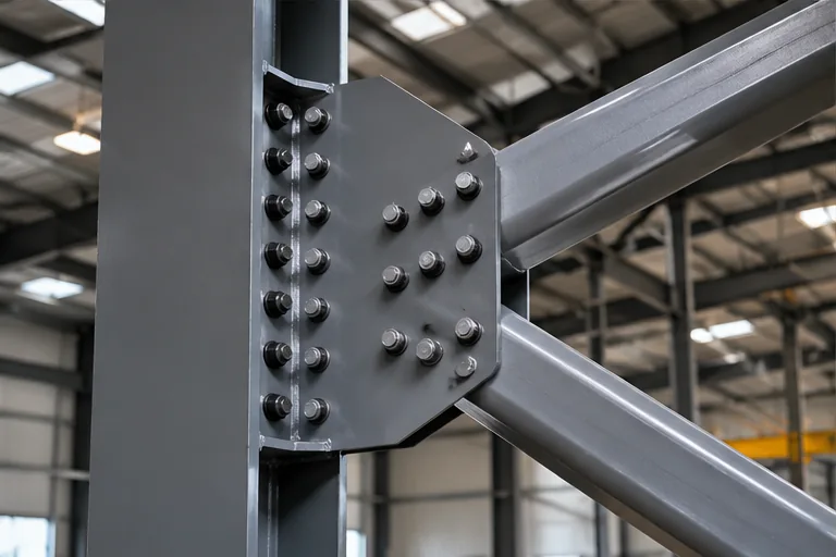
Bracing Gusset Plate Geometry
Aligning diagonal member work points with beam-column centers.
Foundation & Anchor Interface
Anchor rod layouts coordinated with civil and foundation setting-out drawings.
Foundation & Substructure Coordination
Column Base Plates, Anchor Rods and Concrete Interfaces
Column-base detailing depends on both the steel and foundation information. A properly coordinated document set may identify column marks, base plate arrangement, anchor references, offsets, relevant elevations, grout-related interface information and any stiffener or gusset arrangement provided in the structural design.
The anchor pattern shown on the steel drawings must reconcile with the applicable foundation and setting-out documents. Differences between an existing slab or pier and the specified new steel arrangement should be logged for project-team clarification. Drafting alone does not establish anchor capacity, concrete breakout resistance, embedment depth or foundation adequacy.
Typical Base Plate Coordination Checks:
Span Continuity & Transport Breaks
Beam Splices and Special Connection Assemblies
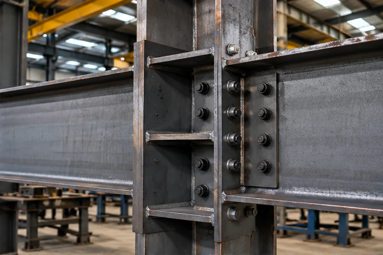
Beam splices introduce a separate set of assembly and fit-up questions. The detailer must know where the splice occurs, which segments are fabricated and shipped, what approved plates or fasteners are required, and how the joint is intended to be completed on site.
The drawings may include top, side or section views; connection plate references; member marks; assembly dimensions drawn from the design; and the documented fastening sequence or attachment responsibilities when supplied by the project. Do not invent erection means and methods, temporary stability systems or engineer-approved splice capacities.
For HSS and specialty connection assemblies, the same principle applies: use connection-specific geometry and approved criteria rather than a copied standard detail when the project conditions differ.
Bolted Beam Field Splice
Coordinating shipping lengths, field access, and bolt hole clearances.
Fastener & Weld Coordination
Bolted vs. Welded Connection Documentation
Bolted and welded connections require different drawing information. The connection type alone does not establish the right bolt grade, hole category, installation method, weld size or inspection requirement. Those decisions are project-specific and may depend on the approved design and referenced specifications.
Bolted connection drawings may document the approved fastener designation, bolt group, hole information, plates, member reference and whether installation is in the shop or field. RCSC guidance is relevant when the project specifies structural joints using high-strength bolts, subject to the contract edition and requirements.
Welded connection drawings may document approved weld locations, symbols, shop/field weld distinctions and coordinated assembly views. AWS D1.1 is a common structural-steel welding reference when the project documents invoke the appropriate edition.
| Topic | Bolted Connection Documentation | Welded Connection Documentation |
|---|---|---|
| Primary location references | Bolt groups, hole patterns, plate position | Weld symbols, joint/part location |
| Key approval inputs | Approved fastener and hole requirements | Approved weld type, size and location |
| Shop and field interface | Installation responsibility and access | Shop versus field welding references |
| Common drawing conflict | Bolt access, clashes, hole misalignment | Fit-up, access, conflicting weld notes |
| Engineering responsibility | Design and joint requirements from responsible engineer | Welded connection design from responsible engineer |
Do not claim that a specified weld or bolted joint complies with a code solely from illustrative pictures.
Professional Boundaries & Scope Division
Detailing vs. Connection Design: Who Is Responsible?
Connection detailing and structural connection design are frequently combined in search results, yet they are different professional activities. For each project, confirm who is responsible for connection criteria, connection design review, calculations or seals, approval drawings and the final release to fabrication.
The Detailer
Prepares the drawing representation, part references, fabrication information and coordination records based on established project requirements. Detailers coordinate fit-up, clearance and layout consistency.
The Connection Engineer
Determines the required resistance and design configuration of the structural joint. Depending on the project's contractual arrangement, this is the responsibility of the engineer of record (EOR) or a qualified, properly engaged delegated-design engineer.
Fabricator & Erector
Include manufacturing and installation duties defined by the contract, approved drawings and applicable standards. A shop drawing does not itself authorize a change to the engineered system.
Proactive Issue Prevention
Common Connection RFIs and Coordination Problems
Connection detailing becomes less reliable when source drawings contain incomplete or conflicting criteria. Questions should be raised early, with the affected member marks and drawing locations recorded.
| Common Issue | Why It Matters | Practical Drawing-Stage Response |
|---|---|---|
Missing connection type or approved reference | The detailer cannot select engineering requirements independently | Request connection detail or delegated design criteria |
Unclear bolt or weld information | Shop and field requirements are ambiguous | Reference design documents; request clarification |
Conflicting column and beam orientation | Plates or bolts may conflict with the actual geometry | Coordinate grid, orientation and model views |
Gusset clashes with nearby framing | Fabricated parts may not fit as shown | Record conflict and resolve with project team |
Anchor pattern differs from foundation drawings | Base plate and concrete interfaces cannot be reconciled | Compare versions and issue coordination query |
Revised member size after connection detailing | Detail geometry may no longer match | Update model and linked drawings following authorization |
Field bolting access obstructed | Assembly or installation constraints may be unresolved | Flag access for fabricator/erector/project-team review |
Superseded revision used for fabrication | Shop may manufacture the wrong component | Confirm current approval and revision status |
3D Modeling & Digital Deliverables
Model Coordination and Fabrication Outputs
Three-dimensional coordination can help project teams view how a steel connection interfaces with adjacent members. Where the contracted workflow includes a structural model, drawing views and model elements should be consistent in member references, orientation and revision status.
PDF is commonly used for submittal review and distribution. Native drawing files, 3D model exports, CNC/DSTV data, DXF plate profiles or related schedules may be included when the fabricator requests and the specific software workflow supports them. No such output should be advertised as universal for every project.
Where a complex connection includes numerous plates, bolts or brace interfaces, coordination images can help reviewers understand the assembly, but model visualization is not a substitute for approved structural design.
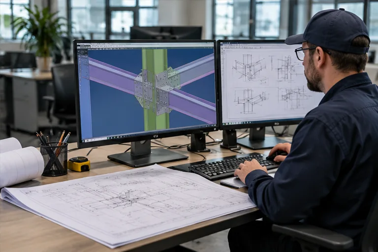
3D Connection Coordination Review
Reconciling structural member geometry, clash detection, and digital plate profiles.
Deliverable Previews
Sample Steel Connection Detail Drawings
These illustrative sheets show how different connection types can be organized for review. They demonstrate component references, conceptual member interfaces, example layout arrangements and a documented review checklist. The sheets do not include engineered dimensions, verified loads, approved fasteners or permitted field instructions.
Illustrative drawing samples only. Not approved for structural design, fabrication, construction, or code compliance verification.
SIMPLE SHEAR FRAMING DETAIL
Scale: 1" = 1'-0"Shear Tab Beam-to-Column Connection
Conceptual supported-beam and shear plate interface showing plate positioning, bolt spacing, and shop weld callouts.
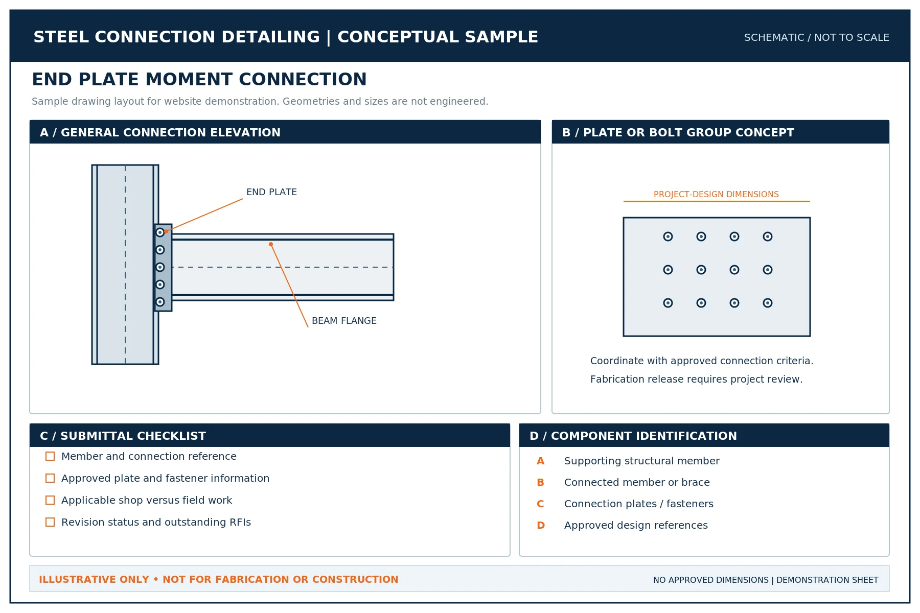
RIGID MOMENT-RESISTING FRAME DETAIL
Scale: 1-1/2" = 1'-0"Moment End-Plate Connection
Illustrative end-plate geometry, tension bolt group references, and continuity stiffener coordination.
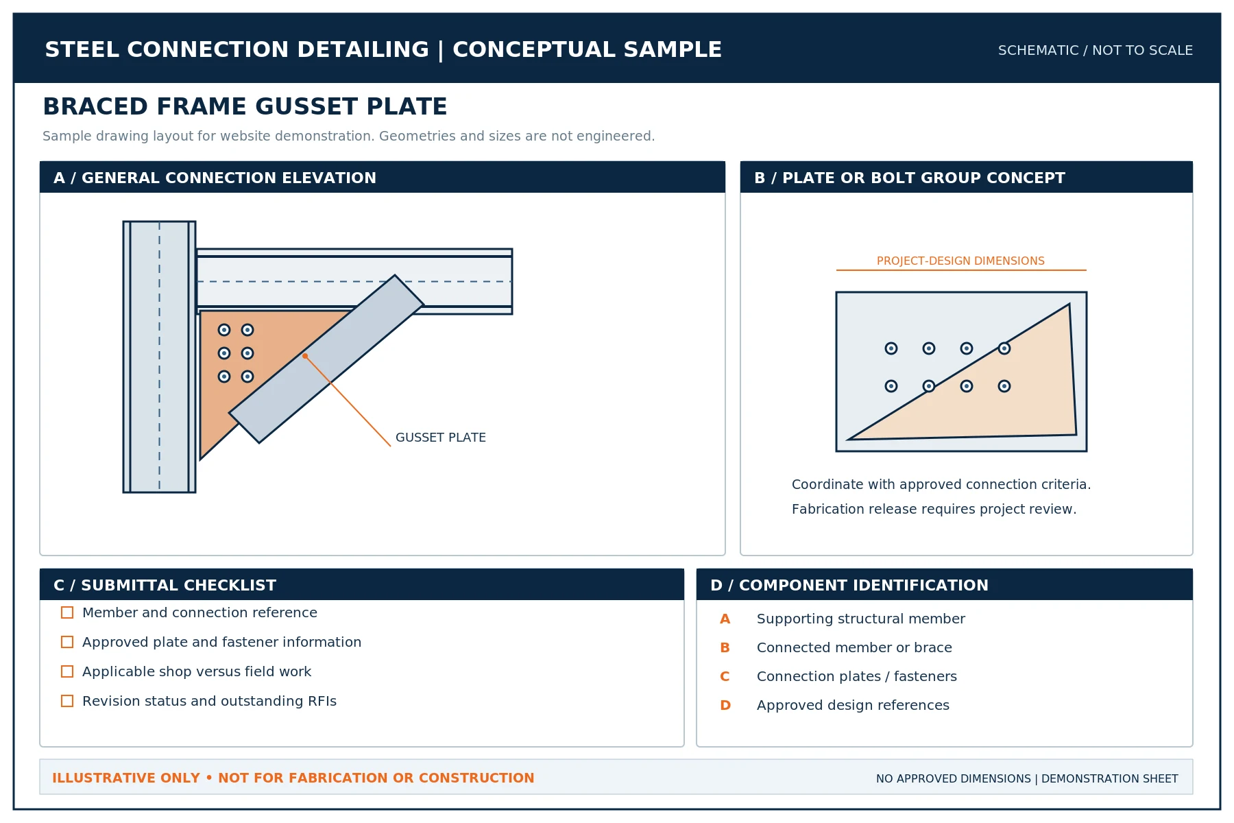
VERTICAL BRACING & WORK-POINT INTERFACE
Scale: 1" = 1'-0"Braced Frame Gusset Plate Connection
Conceptual brace-to-gusset and framing member interfaces with established centroidal work points.
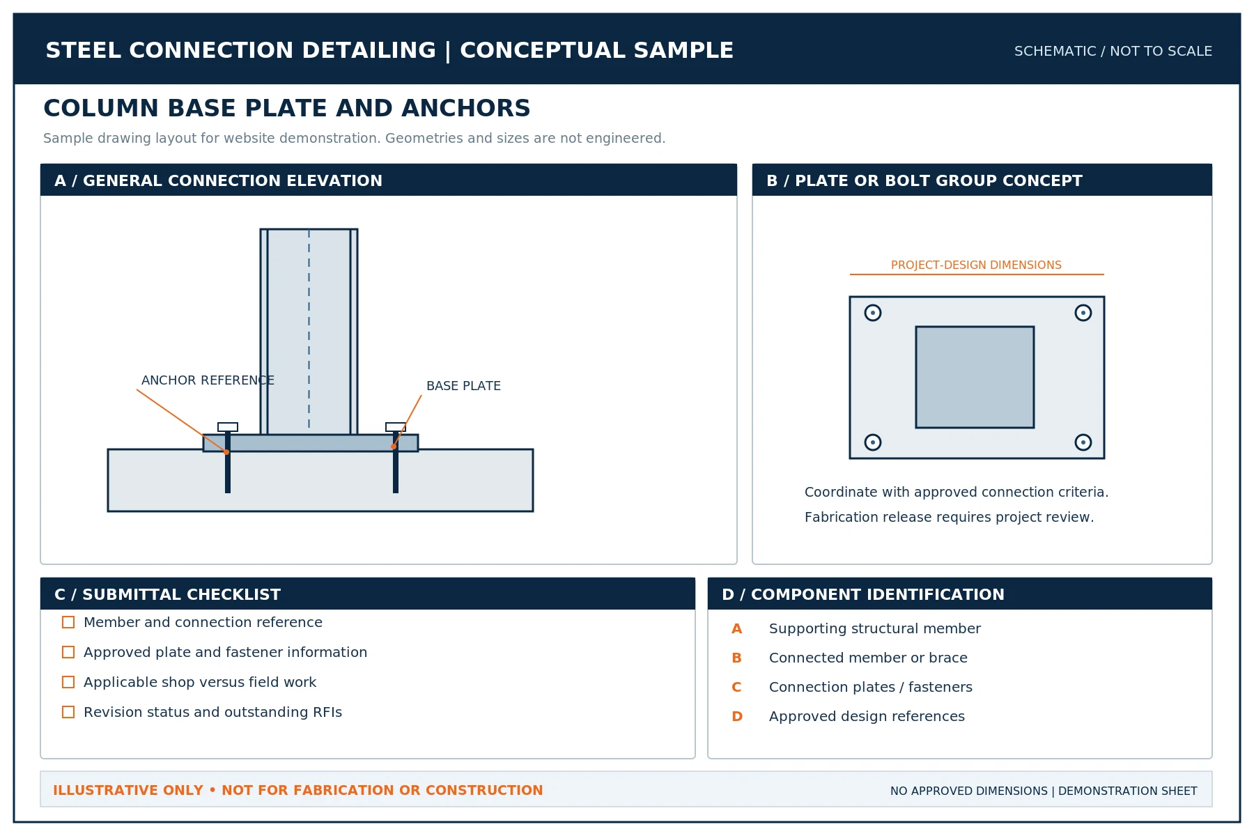
FOUNDATION BEARING & ANCHORAGE SHEET
Scale: 1" = 1'-0"Column Base Plate and Anchor Interface
Schematic column base, anchor rod reference pattern, and leveling grout elevation coordinates.
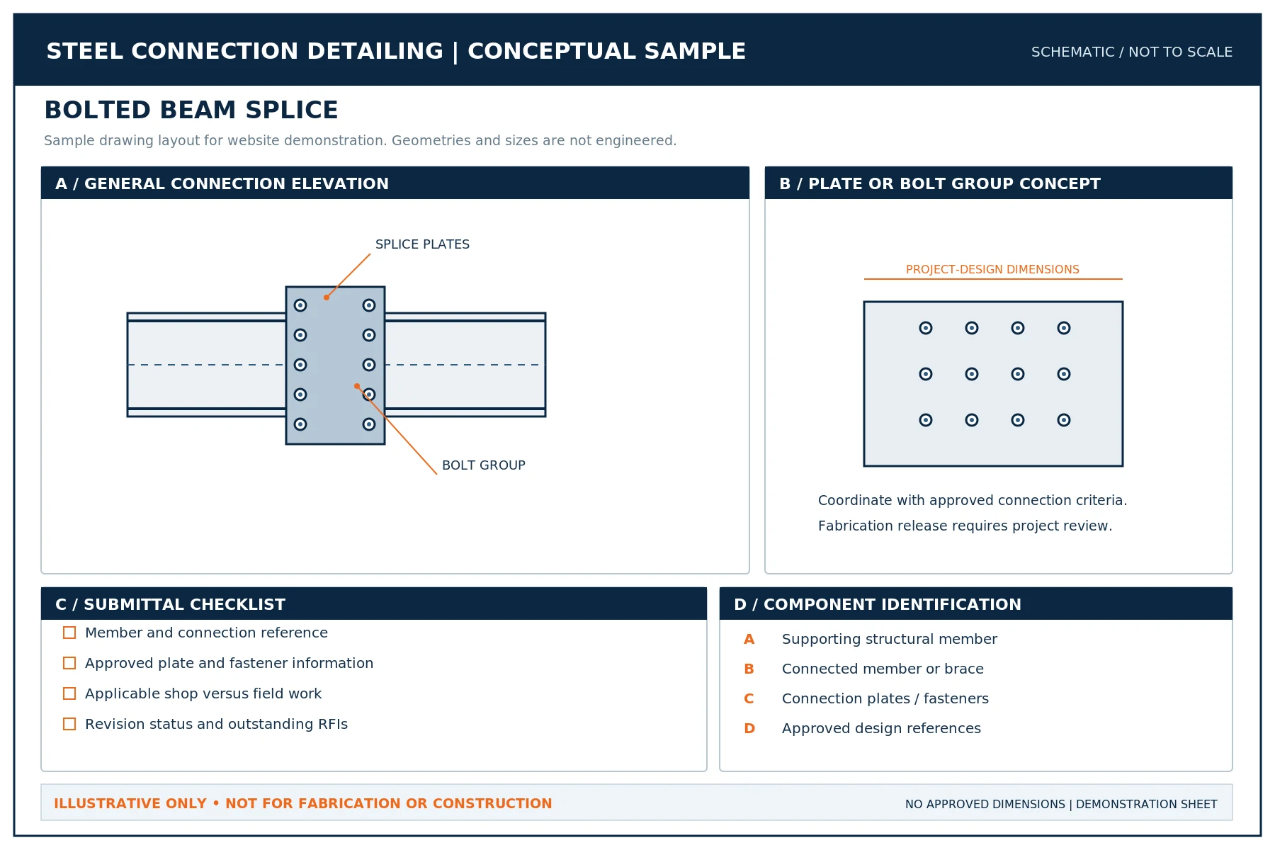
FIELD SPAN SPLICE & CONTINUITY DETAIL
Scale: 1" = 1'-0"Bolted Beam Splice Connection
Example plate arrangement and splice reference showing flange and web field bolting layout.
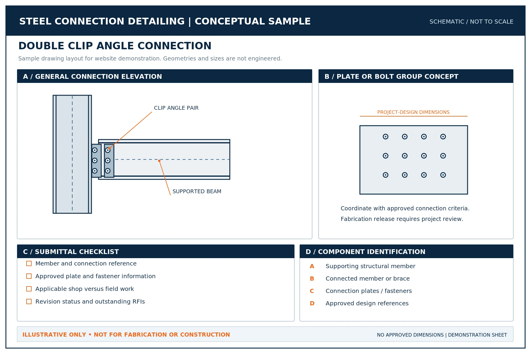
ALL-BOLTED FRAMING BEAM CONNECTION
Scale: 1" = 1'-0"Double Clip-Angle Connection
Schematic angle pair and member interface showing shop-bolted beam web and field-bolted girder attachment.
Quotation Preparation
What We Need to Quote Your Connection Detailing Scope
A useful quotation starts with the actual structural scope rather than an assumed number of drawings. Please send the latest available project documents and identify the connection categories included in the request.
If connection engineering remains open, identify the responsible engineer and the status of their design information. We will not silently fill a missing engineering scope with guessed values.
Submit your available structural drawings through our quote portal for a scope-specific detailing proposal.
Send Project DrawingsProven Production Process
Our Five-Step Connection Detailing Workflow
A structured drafting workflow ensures every connection sheet is verified against project contract documents and authorized engineering criteria.
Confirm the Scope
Identify steel members, connection types, drawing areas, approved criteria, output formats and review stages.
Review Design Info
Check structural plans, standard details, specifications, schedules and latest project revisions. Log missing items.
Prepare Details
Develop connection-specific views, identifiers and related drawings using confirmed geometry and engineering inputs.
Check and Submit
Review sheet references, plate/attachment data, revision status and outstanding coordination items before issuing.
Apply Revisions
Incorporate received design-team comments and approved changes, then reissue details under the agreed process.
Fabrication Quality Verification
Internal checks against contract plans, piece marks, and weld symbols.
Internal Review & Quality Assurance
Connection Drawing Quality Checks
Connection details are most useful when the key information agrees across the drawing set. A review should compare current structural documents, the connection's associated member marks, any approved schedules and the project-specific fabrication requirements.
These checks support document quality. They do not replace structural calculations, engineer-of-record review, fabrication inspection or mandated quality assurance. Review our dedicated Quality Assurance procedures for detailing deliverables.
Industry Codes & Standards
AISC, RCSC and AWS References
Structural steel connection drawings sit within an established framework of contract documents and technical standards, but the applicable edition is determined by the actual project requirements.
These references are not a promise that every connection or illustration automatically complies with every requirement. Connection design criteria, special seismic requirements, welding details and bolting information must be established by the approved project design and relevant responsibility assignments.
AISC 303-22
Addresses standard practice and the relationships among structural steel contracting documents, including communication of design responsibilities.
AISC 303 StandardAISC 360-22
Contains requirements for structural steel design and construction, including connections within its specified scope.
AISC 360 StandardRCSC 2025
Addresses structural joints using high-strength bolts, including design, hole geometry, installation and inspection topics.
RCSC SpecificationAWS D1.1:2025
Structural welding code for steel referenced for welding requirements, symbols, and weld procedures under contract.
AWS D1.1 CodeStakeholders & Applications
Project Types and Who Uses Connection Details
Steel Fabricators
Need member and connection information associated with fabrication assemblies, material preparation and their shop workflow.
General Contractors
Need a clear drawing package for submittal tracking, scope interfaces and coordination with the responsible design team.
Structural Steel Erectors
Use approved placement and connection information in conjunction with their assigned erection plans and site responsibilities.
Design & Detailing Teams
Coordinate structural and connection references as drawings move through review, revision and production.
Applicable Project Environments
Applicable projects include commercial buildings, warehouses, industrial facilities, institutional projects, steel platforms, mezzanines and other structures using structural steel members. These are general applications, not claims of completed company projects. For elevated access steelwork, review our dedicated Steel Platform & Catwalk Drawings service.
Pricing & Timelines
Cost and Schedule Factors for Connection Detailing
There is no responsible universal price or turnaround for every connection drawing package. Effort changes with connection quantity, repetition, design completeness, geometry, required modeling, submittal stage and revision volume.
A group of repetitive shear connections with complete engineer-provided details differs from complex moment joints, braced-frame intersections or retrofit work with uncertain existing conditions. The scope review should establish whether engineering is already complete, which drawing outputs are required and how much coordination may be necessary.
For steel bids and preconstruction planning, teams can also utilize construction quantity takeoffs and estimating support when developing preliminary budgets and steel material quantities.
Common Questions
Steel Connection Detailing FAQs
Clear answers regarding detailing scope, engineering boundaries, file formats, and review workflows.
Need Steel Connection Detailing for Your Project?
Send your structural plans, connection schedules and project requirements. We will review the drawing scope and provide a proposal for the connection detailing deliverables your fabricator or contractor needs.