Framing plans & elevations
Show grids, bay spacing, member marks, top-of-steel elevations, roof slope and building attachment points.
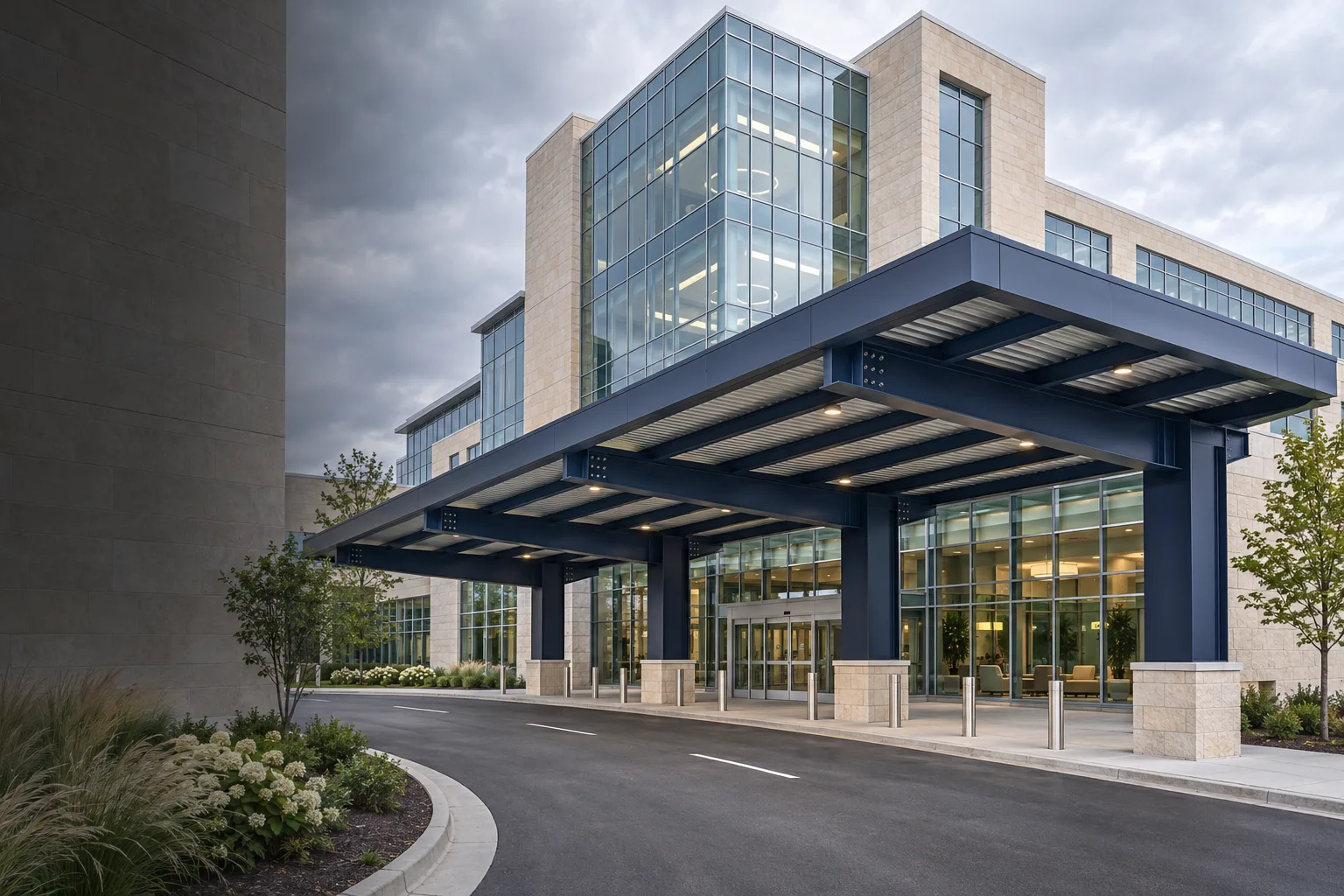
Fabrication and erection drawings for commercial entrances, covered drop-offs and multi-bay steel canopies. Give your shop and field crews a coordinated set for the canopy steel, connections and building interfaces.
Drawing package
Canopies cross several trade scopes in a small area. We detail the steel around the established grid and elevations, then show where it meets the wall, roof, glazing, drainage and supporting structure. The package is scoped for US steel fabricators, specialty contractors and general contractors.
Show grids, bay spacing, member marks, top-of-steel elevations, roof slope and building attachment points.
Document profiles, cut lengths, cope and hole locations, shop welds, plate marks and assemblies using approved criteria.
Coordinate wall plates, hanger brackets, column bases, anchor templates and embeds with the approved design.
Locate assembly marks, field joints and interfaces. Include material lists and agreed model or machine exports when scoped.
Commercial applications
A hospital porte-cochère needs coordinated column locations and clearance over the drop-off lane. A cantilevered office canopy may instead depend on verified wall attachment points and installation access behind a façade. We establish those interfaces before completing piece and assembly drawings.
Canopy types
| Support system | Detailing priorities | Common applications |
|---|---|---|
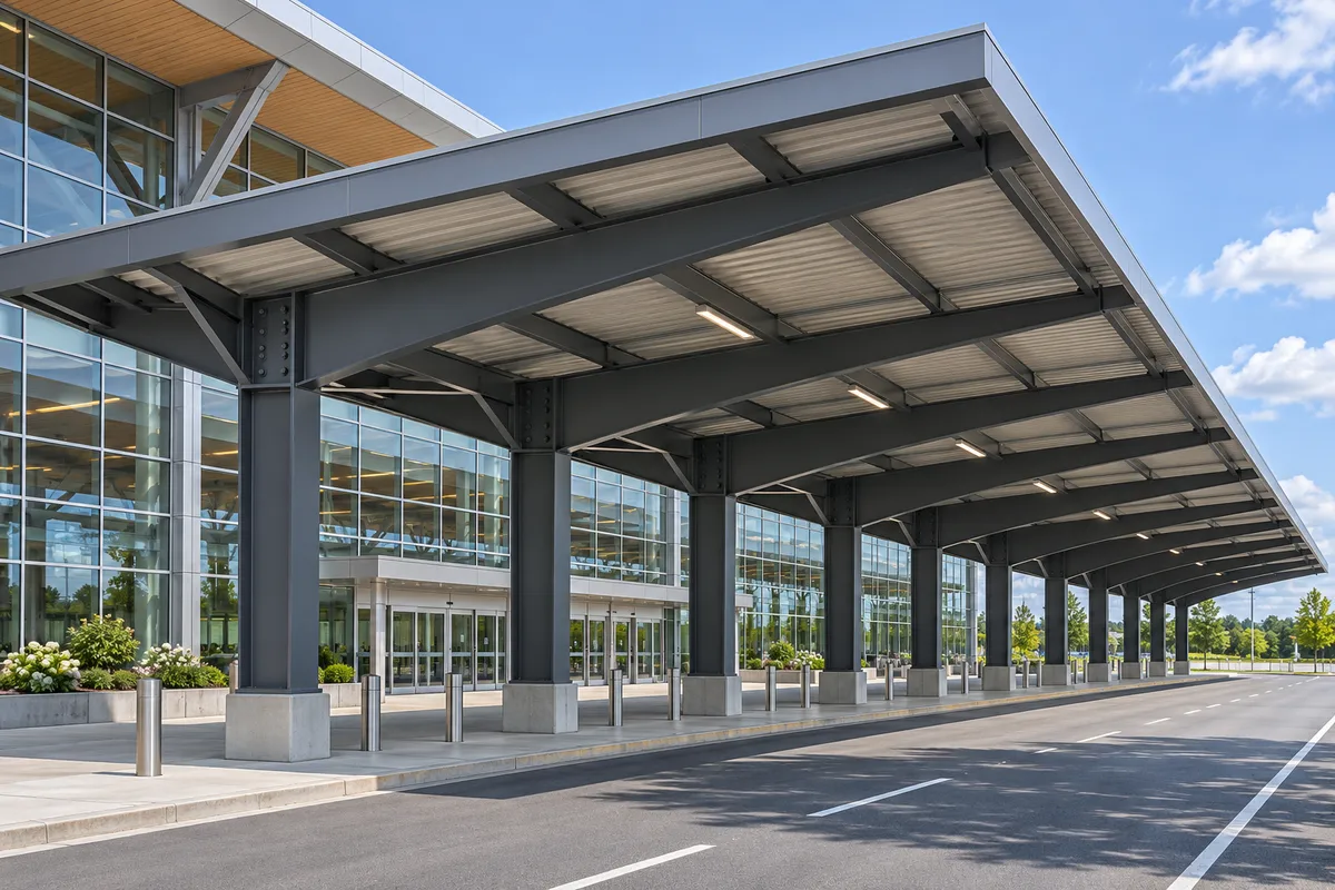
| Wall-supported cantilever | Outrigger spacing, wall plate elevations, attachment substrate and clearance behind the cladding.Office and institutional entrances | Office and institutional entrances |
| Hanger-rod supported | Upper and lower attachment points, rod geometry, clevis clearances and access for installation.Commercial lobbies and public entries | Commercial lobbies and public entries |
| Freestanding or column-supported | Column grids, base-plate orientation, anchor set-out, roof fall and vehicle clearance.Hospitals, terminals and covered drop-offs | Hospitals, terminals and covered drop-offs |
| Long-span and segmented | Assembly breakpoints, field splices, match marks, adjacent trade interfaces and erection references.Convention centers and multi-bay walks | Convention centers and multi-bay walks |
Fabrication and site coordination
A canopy framing plan shows the steel layout. The supporting details tell the shop where it can build repeated assemblies and tell the installer where the steel must fit around the building. These are three areas we review early on commercial canopy projects.
Locate wall plates and hanger brackets from structural grids and floor elevations. On a retrofit, confirm the existing steel or concrete and the finished wall build-up before finalizing attachment locations. Flag discrepancies before the shop cuts or drills the affected pieces.
Show top-of-steel elevations and support locations where roofing, fascia, gutters and downspouts meet the frame. At a commercial drop-off, review the clearance below the lowest finished element against the project’s vehicle clearance requirements.
Use the fabricator’s shipping and handling limits to plan assembly breaks. Carry the same piece marks through the part sheets, assembly drawings and erection plan so the field crew can identify the correct segment and its orientation.
If the architectural elevation locates a hanger rod behind a curtain wall mullion but the structural sheet shows the supporting steel offset from that point, record both locations and request an approved attachment detail. Once the team resolves the conflict, carry the revised location through the canopy elevation, bracket assembly and erection sheet.
Sample deliverables
Explore eight conceptual sheets for large commercial projects. Open a sheet to zoom in on the drawing layout and coordination notes. Illustrative samples only. Do not use them for fabrication or construction.
Sheet 1 of 8
Coordination and review
Check current architectural and structural sheets, canopy specifications, approved details and fabricator standards.
Log missing dimensions and attachment information. Coordinate roof slope, façade returns, drainage paths and access through RFIs.
Build framing, assembly and part drawings around approved geometry. Coordinate piece marks and shop-versus-field work.
Cross-check plans, details and schedules, then issue the agreed package for review. Track responses and revisions through release.
We document the approved geometry, member sizes and connections. The responsible design professional establishes loads, member design, anchor capacity and structural adequacy. If design information is missing, we identify the affected detail and request direction before release.
Follow the adopted code and project specifications. Common references include AISC 303 for approval documents, AISC 360 for structural steel design, ASCE 7 for design loads and AWS D1.1 for structural welding when specified.
FAQs
Scope, approvals and what your fabricator receives.
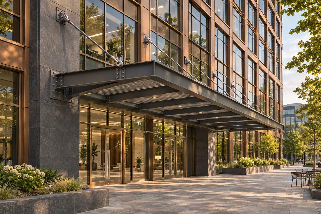
A typical package includes a roof framing plan, elevations and sections, piece and assembly drawings, approved connection details, anchor or embed layouts, and an erection plan. Material lists and digital exports depend on the agreed scope.
Yes, when the team provides verified field dimensions, confirmed substrate information and approved connection criteria. We flag unknown conditions for the contractor and responsible designer before detailing the affected areas.
The responsible licensed design professional establishes loads, reactions and connection design criteria. Our detailing translates the approved design into coordinated fabrication documents. Engineering calculations, delegated design and stamps require a separately defined scope.
Yes. We show the steel interfaces for slope, gutter supports, soffits, fascia, flashing and adjacent cladding using the current drawings and supplier information. Final enclosure and drainage design remain with the responsible trades and design team.
Send current architectural and structural drawings, canopy elevations and sections, specifications, approved connection criteria, available field measurements, and your submittal date. List desired outputs and any shop standards or machine requirements.
Tell us which formats and machine conventions your shop uses. PDF drawing sets and any DWG, IFC, material list or NC/DSTV exports are confirmed in the quote according to the project workflow.
The number of unique assemblies, connection types, façade interfaces, and required file formats all affect the scope. A long canopy with repeated bays may take less detailing than a smaller canopy with several custom connections. Share your bid or submittal deadline so we can account for the review cycle in the quote.
Follow the release procedure in your contract. Confirm that the required reviewers have returned their comments, affected details have been updated, and the fabricator has the current drawing revision for release. Keep preliminary drawings separate from the released set.
Related services
Explore fabrication, connection and anchor drawings for the canopy and adjoining structural steel.
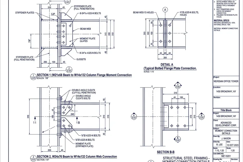
Detail individual steel parts and assemblies with piece marks, hole locations, cut dimensions and weld notes.
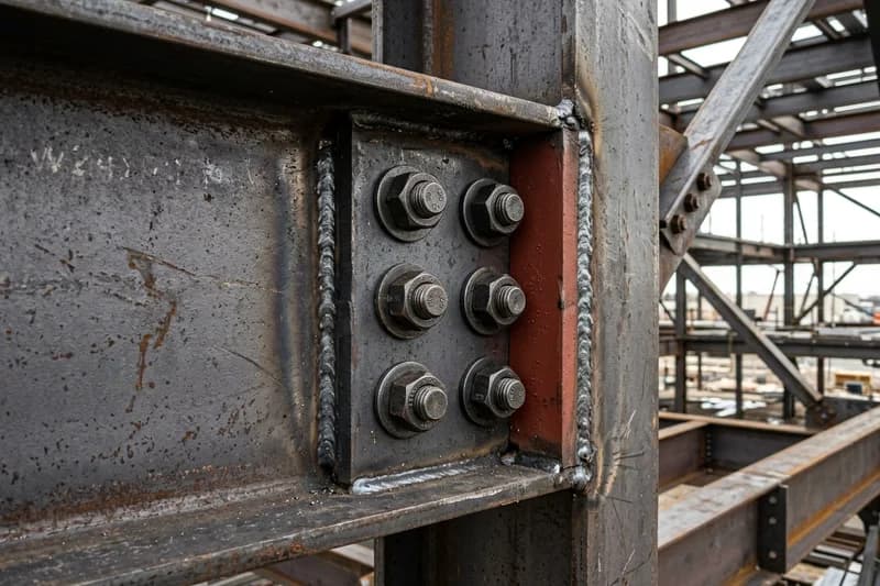
Document approved bolted and welded connections, including splice plates, stiffeners and brackets.
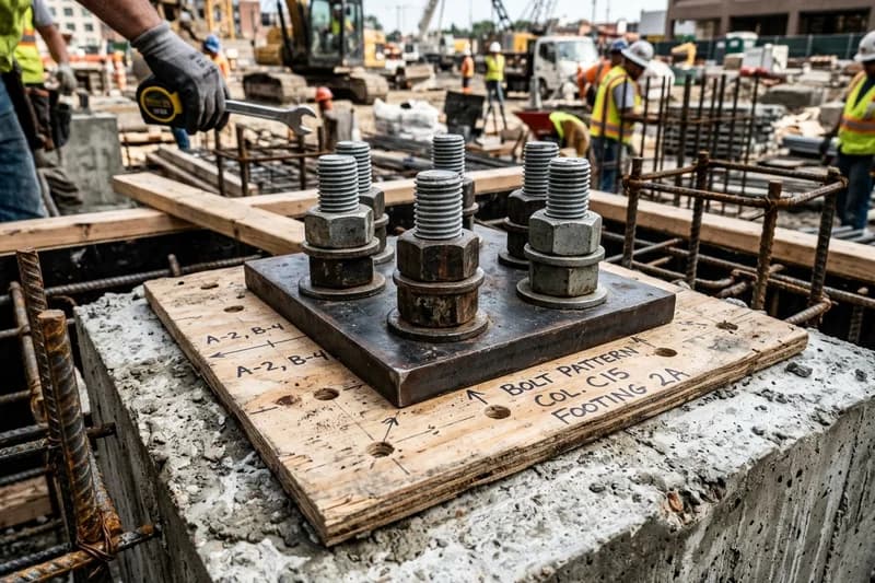
Coordinate anchor locations, templates and embeds with column base plates before concrete placement.
Send the current drawings and let us know what your shop needs for submittal, fabrication and erection. We’ll review the scope and prepare a project-specific quote.