A stair that climbs right but fails egress still fails
A steel stair can be perfectly fabricated and still fail its submittal. The steel is true and the welds are clean, and the reviewer still sends it back, because the risers vary by half an inch, the handrail stops one tread short, or the guard post is anchored to a substrate that cannot carry the load. Stair and railing shop drawings are code drawings before they are fabrication drawings, and a drawing that calls everything a railing has not detailed any of the three.
Who this is for: stair and miscellaneous metals detailers, steel fabricators, general contractors and EOR reviewers who check stair and railing submittals before steel is cut. The short answer: a stair shop drawing that passes review dimensions every flight from finished floor to finished floor, keeps risers and treads uniform, draws the handrail as a continuous grip with extensions, draws the guard as a 42 inch barrier with code-checked infill, and shows the anchorage as a load path to structure.
For the approval step that applies to a stair and railing submittal as much as to a steel submittal, see our structural steel shop drawing submittal checklist, which sets out what the EOR actually checks before approval.
Edition first: name the 2021 IBC, then check local adoption
Before a single line is drawn, confirm the adopted IBC edition, the adopted ADA standard and the project specification, and name them in the submittal. Section numbers, guard heights and load provisions change between editions. This post uses the 2021 IBC as its reference edition, the edition most widely referenced in current guides; the 2024 edition exists but is not yet the adopted edition in most jurisdictions. The local adopted edition and its amendments govern the project, not this post.
In the 2021 IBC, stairs sit in Section 1011, handrails in Section 1014, guards in Section 1015, and handrail and guard loads in Section 1607.9.1. That last number matters: the load section was 1607.8.1 in the 2015 and 2018 editions and was renumbered to 1607.9.1 in 2021, with the load values unchanged. The adopted federal accessibility standard is still the 2010 ADA Standards, Section 505 for handrails; no newer edition exists.
Three devices that share one flight
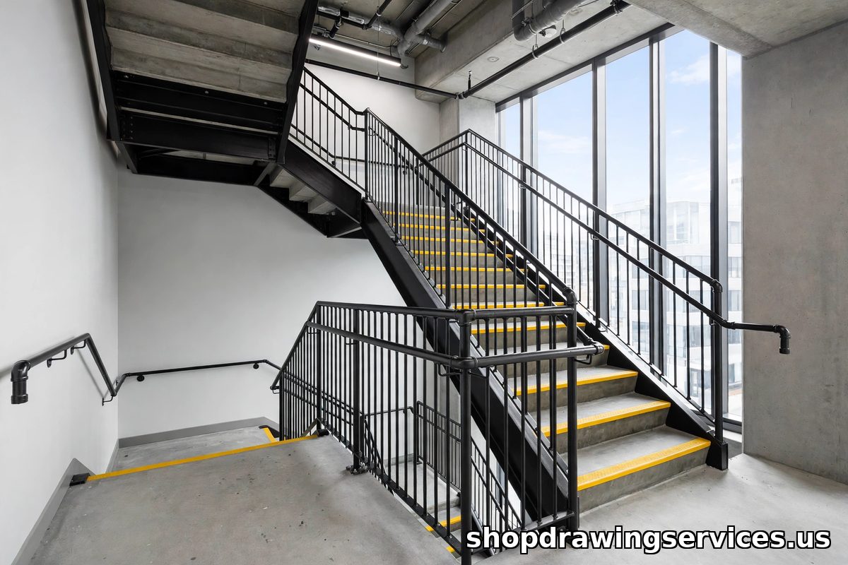
The stair is the walking surface: risers, treads, nosings, landings and the stringer that carries them, governed by egress geometry. The handrail is the graspable rail a person holds while climbing, governed by grip, height and continuity. The guard is the barrier that stops a person falling off an open edge, governed by height, infill and load. One member can serve two functions only when it meets both sets of rules at once. A 42 inch commercial guard is usually too high to serve as a 34 to 38 inch handrail, so a separate graspable rail is then required on the guard or on the wall. Keep the three devices separate on the drawing, with separate heights, profiles and checks.
Stair geometry: dimension from finished surface to finished surface
Every stair dimension starts at finished floor and ends at finished floor, not at steel to steel. Total rise, risers, treads, total run and landing positions are all dimensioned from finished surfaces, so the first riser is not short by one tread thickness and the last riser is not tall by one finish layer. The nosing line must run through every tread nosing point, and the stringer offset from top of steel to the nosing line is a stated dimension, not a field guess.
Under IBC 2021 Section 1011.5, riser height runs 4 inches minimum to 7 inches maximum, tread depth is 11 inches minimum, and the variation in riser height and tread depth inside one flight is limited to 3/8 inch. Headroom is 80 inches minimum above the nosing line under Section 1011.3. Stair width is 44 inches minimum, or 36 inches where the stair serves fewer than 50 occupants, under Section 1011.2. Do not swap in residential IRC figures: IRC risers go to 7-3/4 inches and treads to 10 inches, and those are not IBC figures. Show egress width and headroom as drawn dimensions on plan and section. Stair width is an egress dimension, and a stair narrowed in the field by a guard post or a handrail bracket has failed its drawing.
Stringers, treads and connections are a load path, not a parts list. Show the stringer section, whether channel, plate or rectangular hollow section, the tread type, whether pan, grating or plate, the tread to stringer connection, the landing framing, and the top and bottom connections to the supporting beam or slab, including any dog leg where the stringer cannot connect directly to its support. Show bearing, bolt or weld callouts at each connection, and where the stair is fixed and where it is allowed to move. For connection callouts that delay approval when they are missing or wrong, see our guide to steel connection detailing mistakes. State materials, finishes and slip resistance on the drawing too.
Artifact 1: stair geometry and stringer schedule
Labelled hypothetical flight, not a real project. The fields one flight in section must carry before any rail is drawn.
| Flight item | What the drawing states | Check it against |
|---|---|---|
| Total rise | Finished floor to finished floor, with finish buildups listed | IBC 2021 Section 1011.5 |
| Risers | Uniform, 4 to 7 inches, variation within 3/8 inch in the flight | IBC 2021 Section 1011.5.4 |
| Treads | 11 inches minimum, nosing line through every nosing point | IBC 2021 Section 1011.5.2 |
| Stringer | Section, material, top of steel to nosing line offset | Structural documents |
| Landings | Depth in the direction of travel, framing and support | IBC 2021 Section 1011.6 |
| Headroom | 80 inches minimum above the nosing line, dimensioned on section | IBC 2021 Section 1011.3 |
| Egress width | 44 inches minimum, 36 inches under 50 occupants, clear between rails or guards | IBC 2021 Section 1011.2 |
| Top and bottom connections | Bearing, bolt or weld callouts, fixed point and movement point | Structural documents |
For the erection context this stair assembly is set into, see our guide to how to read a steel erection plan, which covers piece marks, gridlines and field bolt schedules.
The handrail: draw the grip, not a line
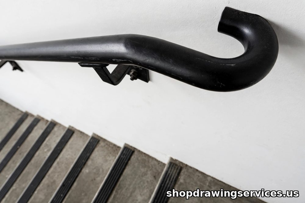
A handrail is drawn as a profile, on elevation and section, not as a single line on plan. The top of the gripping surface sits 34 to 38 inches above the stair nosings, uniform along the whole flight, under IBC 2021 Section 1014.2 and ADA Section 505.4. Most commercial stairs need handrails on both sides. The clear space between a handrail and a wall is 1-1/2 inches minimum so a hand can wrap around the rail, under ADA Section 505.5. Circular rails run 1-1/4 to 2 inches in diameter. Noncircular rails run 4 to 6-1/4 inches in perimeter, with no cross section dimension over 2-1/4 inches, under ADA Section 505.7.
Continuity is where handrails most often fail review. The gripping surface must run continuously along the flight, and a handrail that stops at the last riser, or that is interrupted by a newel post without a continuous grip, is not a handrail. Show the top extension, 12 inches minimum horizontally beyond the top riser, and the bottom extension following the slope for at least one tread depth, under ADA Section 505.10, with returns that do not snag clothing or a hand. Draw the extensions on the elevation, with dimensions.
ADA scope must be stated plainly on the submittal. ADA handrail rules apply to stairs that are part of an accessible route in covered public and commercial buildings, under Sections 504 and 505 of the 2010 ADA Standards. State which stairs on the project are in that scope and which are not. ADA does not generally apply to an ordinary private home. On wide stairs, where a person is more than 30 inches from a graspable rail, an intermediate handrail is required, and the drawing must show its position, height, grip and support.
Artifact 2: handrail and guard profile sheet
Labelled hypothetical bay, not a real project. The fields one bay in elevation and section must carry for the handrail and the guard, side by side, so neither device is checked against the other's rules.
| Profile item | Handrail | Guard |
|---|---|---|
| Height | 34 to 38 inches above the nosings, uniform along the flight | 42 inches minimum above the nosing line on stairs |
| Checked as | Graspable rail: grip, continuity, extensions | Barrier: height, infill, load at the anchorage |
| Grip or infill | Circular 1-1/4 to 2 inches diameter, or noncircular 4 to 6-1/4 inches perimeter | 4 inch sphere to 36 inches, 4-3/8 inch sphere from 36 to 42 inches, 6 inch sphere at the stair triangle |
| Clearance | 1-1/2 inches minimum clear from the wall | Bottom rail position and baluster spacing dimensioned |
| Extensions | 12 inches minimum beyond the top riser, slope extension at the bottom for one tread depth, with returns | Not applicable, the guard runs the full open edge |
| Wide flight | Intermediate handrail where a person is more than 30 inches from a graspable rail | Intermediate posts sized and spaced for the guard load |
The guard: height, infill and the sphere bands
A guard is required along open-sided walking surfaces, including stairs, landings, balconies and mezzanines, where the walking surface is more than 30 inches above the floor or grade below, measured within 36 inches of the edge, under IBC 2021 Section 1015.2. Commercial guards are 42 inches minimum under Section 1015.3, measured vertically from a line connecting the leading edges of the tread nosings on stairs. Residential guards are 36 inches under the IRC, and the two numbers must never be swapped. A 36 inch guard on a commercial stair is a failed guard.
The infill rule is banded, not flat, and the flat version is the error most often drawn. Under IBC 2021 Section 1015.4, openings must not allow passage of a 4 inch sphere up to 36 inches in height, and from 36 inches to 42 inches the limit is a 4-3/8 inch sphere. The triangular opening at the open side of a stair, formed by the riser, the tread and the bottom rail, must not allow passage of a 6 inch sphere. The drawing must show baluster or panel spacing, bottom rail position and the stair triangle with those three sphere checks stated, because the triangle is where the sphere rule is most often failed. A baluster layout that passes the 4 inch check on the landing can still fail the triangle on the flight.
Guardrail anchorage: the load is the design
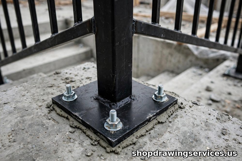
Anchorage is where most guard submittals are weakest, because the post looks strong and the anchorage is drawn as an afterthought. The load is the design, not the post. Under IBC 2021 Section 1607.9.1, guards and handrails are designed for a 200 pound concentrated load applied in any direction at any point along the top rail, plus a 50 pound per linear foot uniform load at the top, and infill must resist 50 pounds over one square foot. The uniform and concentrated loads need not be assumed to act concurrently. The drawing must state the adopted IBC edition and section and show the load path from top rail to post to anchorage to structure.
A surface mounted base plate resists the overturning load as a moment couple, through tension in the anchors on one side and compression bearing on the concrete or steel on the other. The drawing must show plate size and thickness, anchor type, diameter, embedment and edge distance, grout or levelling detail, and the substrate the anchors land in. Anchor type, embedment, edge distance and substrate capacity come only from the adopted code, the project structural documents and the anchor manufacturer's data. This post states no anchor embedment, plate thickness or bolt size, because no such figure can be taken from a guide. A base plate detail copied from a wood deck onto a concrete stair has not been designed. Bolts through a rim joist alone, without a tie back into the framing, do not typically meet the load.
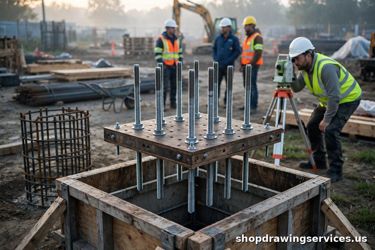
The substrate must be checked, not assumed. The structural element must be able to carry the base reactions, anchor locations must be coordinated with embedded items, reinforcement and post tensioning, and delegated design calculations and sealed shop drawings must go to the engineer of record where the project requires them. For the setting plan and embed plate work this post builds on at stair and railing bases, see our guide to anchor bolt setting plans, which covers the mistakes found only after the concrete pour. Close the detail with weld size and type, the shop weld versus field bolt split, and shim allowance so a post out of plumb can be set plumb.
Artifact 3: guard post anchorage coordination checklist
Labelled hypothetical, not a real project. The substrate coordination items that must be confirmed before fabrication, because every one of them is a reason a guard submittal comes back.
- Adopted IBC edition and load section stated on the drawing, 1607.9.1 for a 2021-edition submittal
- Load path drawn from top rail to post to base plate to anchorage to structure, with the moment couple shown
- Base plate size and thickness, anchor type, diameter, embedment and edge distance, all stated on the detail
- Substrate identified, concrete strength and thickness, steel member size, or wood framing, with capacity confirmed
- Anchor locations coordinated with embedded items, reinforcement and post tensioning in the slab or beam
- Grout or levelling detail and shim allowance stated, so a post out of plumb can be set plumb
- Weld size and type at post to plate and rail to post, with shop weld versus field bolt split stated
- Delegated design calculations and sealed shop drawings routed to the engineer of record where the project requires them
The 7-step shop checking sequence
- Edition first. Confirm the adopted IBC edition, the adopted ADA standard and the project specification before drawing, and name them in the submittal.
- Fix the geometry. Total rise and run from finished surfaces, uniform risers and treads, nosing line, landings and egress width, before any rail is drawn.
- Separate the three devices. Stair, handrail and guard each get their own height, profile and load check, and any member serving two functions is checked against both sets of rules.
- Draw the grip. Handrail profile, diameter or perimeter, wall clearance, continuity, extensions and returns, on elevation and section.
- Draw the guard. Height, infill spacing with the banded sphere check, bottom rail and stair triangle, and intermediate handrails where the width requires them.
- Design the anchorage. Post spacing, base plate, anchors and substrate, with the load path to structure and the delegated calculations where required.
- Reconcile revisions. Re-run the egress, grip and anchorage checks after every accepted move.
What to send with the submittal
A stair and railing submittal that passes first review sends the stair geometry schedule, the handrail and guard profile sheet, the anchorage detail with its coordination checklist, the adopted edition statement, and the delegated calculations where the project requires them, in one package. The reviewer should be able to check the egress width, the grip, the sphere bands and the load path without asking for a missing sheet.
Our structural steel detailing team prepares stair, railing, guardrail and handrail shop drawings to the adopted IBC edition and the project specification, with the geometry, the grip and the anchorage drawn as one coordinated package. Send your stair scope and the adopted code edition through our contact page, and we will confirm what the submittal needs before fabrication starts.