The short answer: LOD 350 coordinates a model, LOD 400 fabricates from it
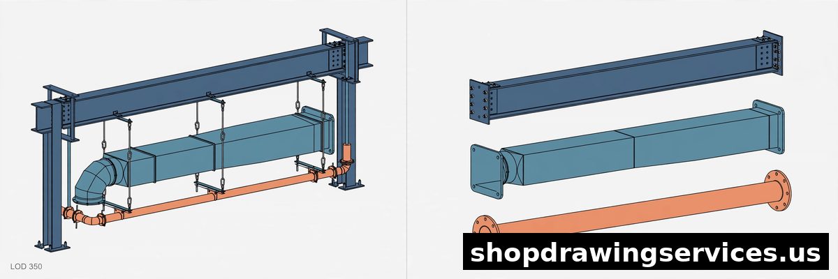
Short answer: LOD 350 gives a fabricator coordinated geometry for an element, with its interfaces, supports, and connections modelled so it can be clash-checked against neighbouring systems. LOD 400 gives the same element with detailing, fabrication, assembly, and installation information added, at detail and accuracy sufficient to fabricate that component. The difference is not simply more detail. It is whether the information needed to cut, assemble, and install that specific element is present in the model for that element. A model described only as "LOD 350" or "LOD 400" with no per-element statement has specified nothing a fabricator can enforce, because Level of Development applies per model element, not to a whole model at once.
Who this is for: steel fabricators, millwork shops, MEP subcontractors, general contractors, BIM coordinators, architects, and engineers in the United States who receive, price, or build from BIM models and need to know what a stated LOD level actually entitles them to rely on before anything is cut.
Our BIM coordination service works at the level the contract actually requires for each element, and names that level per element, so a coordination model is never silently handed over as a fabrication model.
LOD applies per element, and that changes everything
The Level of Development framework comes from the American Institute of Architects, which introduced five levels in its 2008 E202 exhibit, and from the BIMForum Level of Development Specification, which added LOD 350 between 300 and 400 for elements coordinated for clash detection and avoidance. LOD 350 is not an AIA original level, and it is not a software vendor invention.
That per-element point is the whole discipline. A BIM execution plan that says "model to LOD 350" and stops there has said almost nothing. Steel members, duct runs, pipe spools, and curtain wall mullions are separate rows, each with its own level, author, and exclusions. A steel beam at LOD 400 beside a duct run at LOD 300 is a coordination risk, not a fabrication release. The fabricator's first job on receiving a model is to read the LOD matrix and find out, element by element, what level each item was actually delivered at.
What LOD 350 actually means
Paraphrased from the BIMForum definition, an element at LOD 350 is graphically represented as a specific system, object, or assembly in terms of quantity, size, shape, location, orientation, and interfaces with other building systems. Parts necessary for coordination of the element with nearby or attached elements are modelled, including supports and connections. The quantity, size, shape, location, and orientation of the element can be measured directly from the model without referring to non-modelled information such as notes or dimension callouts. Non-graphic information may also be attached to the element.
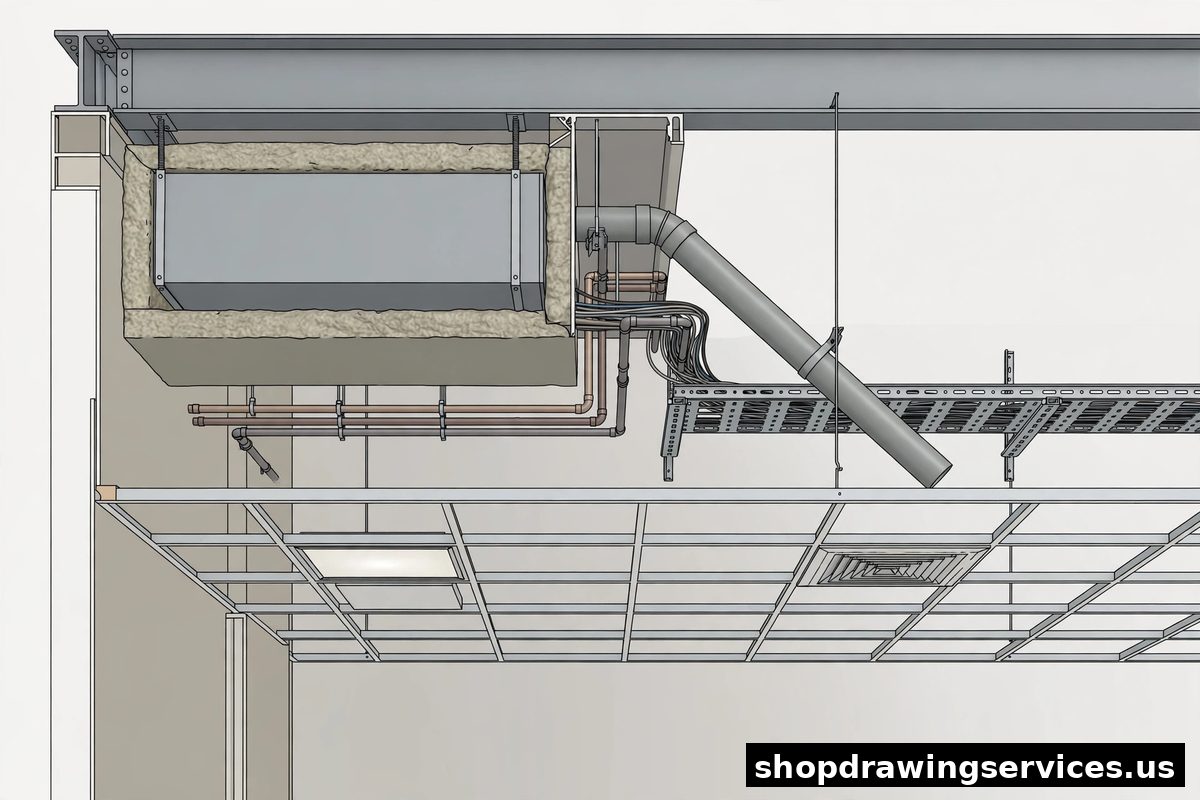
Read that definition slowly, because its limits are its value. At LOD 350, the element is a real, measurable thing in its real place, with the parts that take space around it included. That is why LOD 350 is the coordination level, the level at which a plenum can be checked and a support seen clashing with a tray before anyone is on a ladder. Our guide to MEP coordination in tight ceiling plenums runs on exactly this input: supports, hangers, insulation, sleeves, and access clearances modelled, not left as notes, so the section can be trusted.
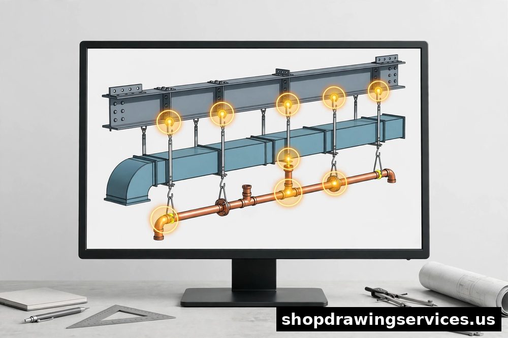
What a fabricator gets at LOD 350, and what they do not get
At LOD 350, a fabricator gets coordinated geometry they can measure, the element's interfaces with neighbouring systems, and the supports and connections needed to coordinate it. That is enough to plan sequencing, to clash-check, and to judge coordination risk, and to see that a duct main will not clear a beam once insulation and a hanger are added. It is not enough to cut from.
At LOD 350, a fabricator does not get fabrication-ready dimensions for every piece, piece marks tied to a cutting list, manufacturer or fabricator specific product data, weld and bolt detailing at fabrication level, tolerances, finishes, or installation instructions for that element. A 350 element still needs shop drawings and a submittal review before anything is cut. Cutting from a 350 model on the assumption that measured geometry equals a fabrication dimension is the central mistake this post exists to prevent. Measured geometry tells you where the element sits and how big it is. It does not tell you how it is made, how it is joined, or in what order it goes together.
What LOD 400 actually means
Paraphrased from the BIMForum definition, an element at LOD 400 is graphically represented as a specific system, object, or assembly in terms of size, shape, location, quantity, and orientation with detailing, fabrication, assembly, and installation information. The element is modelled at sufficient detail and accuracy for fabrication of the represented component, and its quantity, size, shape, location, and orientation can likewise be measured directly from the model. Construction documentation at this level includes final coordinated manufacturer and fabricator information and details.
That last sentence is doing heavy work. Final coordinated manufacturer and fabricator information means the element is no longer generic. It is the product that will actually be installed, with the fabricator's own details, not a placeholder that looks like it. A steel connection at LOD 400 carries the plates, bolts, and welds that will be made, and a duct run at LOD 400 carries the fabrication detail that feeds a cutting list.
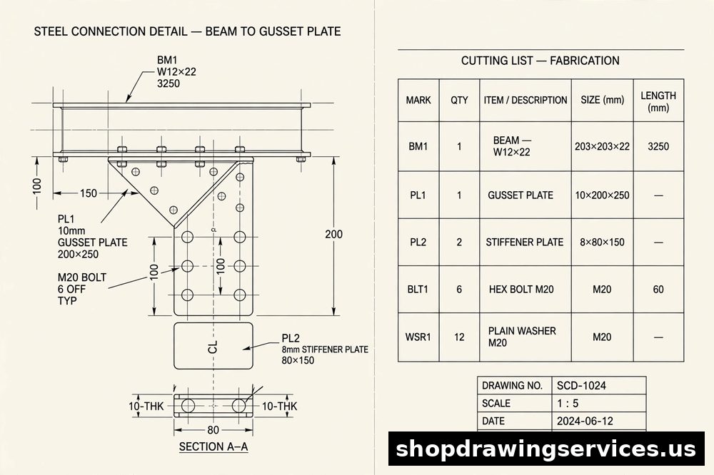
What a fabricator gets at LOD 400, and what they still do not get
At LOD 400, a fabricator gets detailing, fabrication, assembly, and installation information for the element, final coordinated manufacturer and fabricator information, and geometry accurate enough to fabricate the component. That is what feeds shop drawings, cutting lists, and fabrication data. It is the level at which a model stops being a coordination picture and starts being a production input.
At LOD 400, a fabricator still does not get an approved shop drawing by virtue of the model alone, a guarantee that every other element in the same model is also at 400, or as-built truth. Approval remains a separate step. Our guide to shop drawings versus fabrication drawings versus erection drawings explains why those sets are different documents with different readers, and a model, however detailed, does not collapse them into one. The approval step that LOD 400 does not replace is set out in our structural steel shop drawing submittal checklist. Field verification also remains separate: a 400 element is a fabrication instruction, not a record of what was actually installed.
Artifact 1: per-element LOD request matrix excerpt (hypothetical)
This matrix is hypothetical. Real matrices name the project, the model version, and the element types on that job, and they are agreed in the BIM execution plan before modelling starts.
Element | At LOD 350, you get | At LOD 400, you also get | Still missing at each level |
|---|---|---|---|
Steel beam | Accurate size, location, and orientation, with bearing, supports, and connections to neighbouring elements modelled | Connection plates, bolt patterns, weld details, piece mark, and cutting data for that member | At 350: all fabrication detail. At 400: engineer approval and field verification |
Duct run | Accurate size and route, with hangers, insulation, and interfaces to diffusers and structure modelled | Fabrication sections, joint and seam detail, damper positions, and a cutting list | At 350: fabrication sections and joint detail. At 400: approval and field verification |
Pipe spool | Accurate size and route, with supports, sleeves, and interfaces to equipment and structure modelled | Spool breaks, weld and joint detail, piece marks, and installation sequence for that spool | At 350: spool breaks and joint detail. At 400: approval and field verification |
Curtain wall mullion | Accurate size and location, with anchors, perimeter interfaces, and movement joints modelled for coordination | Final manufacturer profiles, anchor details, gaskets, seals, and installation detail for that mullion | At 350: manufacturer and anchor detail. At 400: approval and field verification |
Four traps that turn a good model into a bad cut
First, LOD 300 is not LOD 350. LOD 300 gives precise geometry and location for the element itself. LOD 350 adds the interfaces, supports, and connections that let it coordinate with other systems. A model described as 300 that is used as if it were 350 will coordinate badly: a duct without its hanger clears on screen and clashes in the ceiling. If the scope was priced at 300, adding hangers, insulation, and access later is rework, and rework agreed late is an argument. Agree the level per element before modelling starts.
Second, LOD 500 is not a higher level of detail than LOD 400. LOD 500 is a field-verified as-built record of what was installed. It is not a fabrication upgrade, and a 500 deliverable is not a substitute for 400 fabrication information. Asking for LOD 500 when you need fabrication detail is asking for a record of a building that has not been built yet.
Third, Level of Development is not Level of Detail, and neither is a software export setting. A dense, pretty model is not automatically a 400 model, and a sparse model is not automatically a 350 model. What counts is whether the specified information for that element is present and measurable, per the BIMForum definition. A model with every bolt head drawn but no manufacturer data, no tolerances, and no installation sequence has not reached 400 for that element, however good it looks in a rendering.
Fourth, a blanket level is not a specification. "LOD 400 model" on a proposal, with no matrix, no author per element, and no exclusions, is a sentence a fabricator cannot enforce. The matrix prevents that argument, because it names the element, the level, and what is excluded, before anyone has spent money cutting.
What to ask for, before cutting
Ask for a per-element LOD matrix in the BIM execution plan, naming the level for each element type as separate rows, not one blanket level. Steel members, duct runs, pipe spools, and curtain wall mullions each get their own row, with the level, the author, and the delivery date for that element.
Ask who authors each element at each level, and who owns it when it moves from 350 to 400. A fabricator must not be handed a coordination model and asked to warrant it as a fabrication model. The party that adds fabrication detail needs to be named before the move, not discovered after a failed submittal.
Ask what is excluded at the stated level, in writing. Manufacturer data, tolerances, finishes, piece marks, or installation sequence, whichever applies, should be listed as excluded where they are excluded. Silence on an exclusion is how a 350 model gets cut from. If the proposal does not list exclusions, write them into the reply and ask for confirmation.
Ask about model versus drawing precedence for the contract at hand. If the shop drawing governs, the model level does not override it, and vice versa. Check the contract, do not assume it.
Ask for a re-check trigger. Any element that arrives at 350 inside a package promised at 400 is a hold, not a "close enough" release. One element short of fabrication information is one element that cannot be cut.
Artifact 2: the 350 to 400 gap checklist, per element
Run this checklist on each element type in the package, not on the model as a whole.
Supports modelled: hangers, brackets, and bearing conditions for the element are in the model, not in notes.
Connections modelled: the element's connections to neighbouring systems are in the model at the stated level.
Manufacturer data attached: final coordinated manufacturer or fabricator information for the element is attached, not a generic placeholder.
Piece marks assigned: every piece that will be cut carries a mark tied to a cutting list.
Tolerances stated: the fabrication and installation tolerances for the element are stated in the model or its attached data.
Installation information present: assembly and installation sequence for the element is present, not left to the field to invent.
Submittal route named: the shop drawing and approval route for the element is named, and the model alone is not treated as approval.
An element missing any one of these lines is a hold for that element. A package with one held element and nineteen complete elements is nineteen elements released and one element held, not a package released.
Artifact 3: RFI template for missing fabrication information
Copy this structure into the project RFI form. The hold sentence at the end is the point of the RFI, not an optional extra.
RFI field | What to write |
|---|---|
Element | The element type and piece or zone, for example the level 2 corridor duct main, bay 3 to bay 5. |
Promised level | The level the BIM execution plan or proposal promised for that element, for example LOD 400. |
Level actually received | The level the delivered model actually meets for that element, for example LOD 350, with the missing items listed. |
Specific missing item | The exact item, for example fabrication sections and joint detail for the duct main, or bolt patterns for the beam connection. |
Hold on cutting | "Cutting for this element is on hold until the missing fabrication information above is supplied and the element is reissued at the promised level. No other element in the package is affected by this hold." |
That last sentence protects both sides. It stops the held element from being cut on incomplete information, and it stops the hold from being read as a stop on the whole package.
What to send, so a model gets released the first time
Send the BIM execution plan extract with the per-element LOD matrix, naming the level, the author, and the exclusions for each element type. Send the model version and date, with the discipline models and their dates listed. Send the gap checklist above, completed per element, with held elements named. Send questions early: where an element arrived at 350 inside a 400 package, where manufacturer data is still generic, or where tolerances are unstated, ask before cutting, not after the steel is on the truck.
If your next package arrives with a blanket LOD claim and no matrix, send the proposal and the model version before cutting starts. Our team will check the set element by element against the checklist above, mark what is genuinely at 400, and list what is still at 350 with the RFI wording for each held element. Start with our contact page and tell us the element types in the package, the level promised for each, and the level you actually received. Those three facts decide most of the release that follows. See our quality assurance process, covering the two stage review every set goes through before it leaves the office, and our shop drawing services hub for the full trade list.