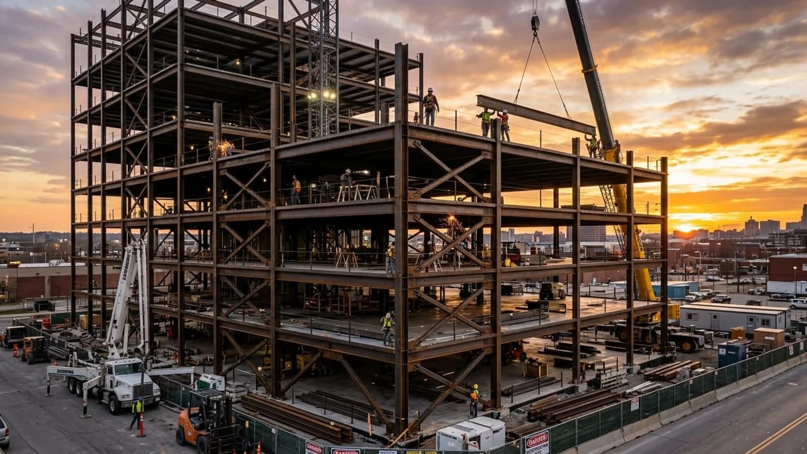
A plumbing riser and a sprinkler main in the same shaft still clash
Two wet systems share the same shafts, ceilings and riser diagrams, and that is exactly why they clash. One system is mostly gravity: sanitary and vent lines that cannot be jogged up over an obstruction the way a pressure line can, and that lose their function if their slope is broken. The other is mostly pressure: a sprinkler main and branch lines that can route around an obstruction, but whose heads must land in a precise ceiling position, clear of beams, ducts, lights and other ceiling devices, or the coverage the system was designed for does not exist in the room.
Who this is for: plumbing and fire protection detailers, MEP coordinators, sprinkler contractors and general contractors who review shop drawings before pipe is cut. The short answer: a plumbing shop drawing that passes review shows riser diagrams floor to floor, zones its shafts before routing, sets gravity slopes first and draws vents, cleanouts and access as installable items. A sprinkler shop drawing that passes review lays every head on the reflected ceiling plan, draws risers, mains and branch lines as a readable system, and braces the piping by calculation from the adopted NFPA 13 edition, not by habit.
For the coordination workflow this post builds on, see our guide to MEP coordination in tight ceiling plenums, which sets the gravity-first sequence and the clash detection workflow for duct, pipe and cable tray in the same space.
Edition first: the two codes that govern this submittal
Before a single line is drawn, confirm the adopted NFPA 13 edition and the adopted plumbing code for the project jurisdiction, and name both in the submittal. A 2025 edition of NFPA 13 exists, issued August 29, 2024 with an effective date of September 18, 2024, but that does not make it the adopted edition in every jurisdiction. Chapter numbers, tables and exceptions change between editions. In the 2019 edition, the seismic protection provisions sit in Chapter 18; in other editions the numbering differs. A drawing that cites one edition while its calculations use another will come back.
The adopted plumbing code varies by jurisdiction: some cities adopt the International Plumbing Code, others the Uniform Plumbing Code, and local amendments change both. Every slope, size and vent figure must come from the adopted code and the project design documents. This post states none of its own.
What the plumbing shop drawing must carry
A plumbing shop drawing is a fabrication and installation instruction, not a redraw of the design layout at a larger scale. What a shop drawing still is when a model exists is covered in our guide to shop drawings vs fabrication drawings vs erection drawings. On the plumbing set, five items separate a submittal that installs cleanly from one that generates field RFIs. Here they are.
Riser diagrams, not just floor plans
Domestic cold, domestic hot and recirculation, sanitary, vent and storm systems must be shown floor to floor, so the reader can see which stack serves which fixtures, where branches tie in, where pressure-reducing valves and recirculation loops sit, and where vents terminate above the roof. The riser diagram is where a sprinkler main crossing a shaft at the wrong elevation gets caught.
Shaft zoning, stated before routing
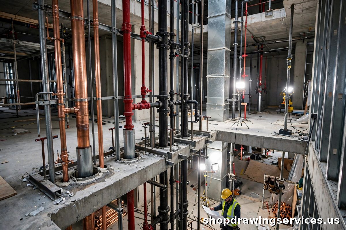
Shafts are finite, and the plumbing risers, the sprinkler riser, duct risers, cable trays and structural elements all claim the same space. Allocate shaft real estate by system zone in the riser diagram and in the model, and show slab and shaft penetrations, sleeves and fire-stopping intent where each riser passes a floor. Freeze that zoning before routing starts.
Gravity first
Set sanitary and storm slopes from the design, then route pressure plumbing, then the sprinkler main and branch lines around them. A sprinkler branch rerouted over a drain is a coordination change. A drain rerouted over a beam to clear a sprinkler main is a design failure, and the drawing must say which one happened and why. Gravity cannot negotiate: a pressure line can drop under an obstruction and rise again, but a drain that loses its slope stops draining.
Vents, cleanouts and access, drawn as installable items
Vent stacks need clear vertical runs that do not land on a beam. Cleanouts must sit where a person can actually reach them. Valves and backflow assemblies need service clearance, and access panels belong above ceilings where a valve, trap or joint will need maintenance. A cleanout behind a fixed ceiling panel is not a cleanout. If the access panel is not on the drawing, the installer will not cut one.
Fixture tie-ins and invert levels
Branch drains to fixture groups carry pipe sizes, slopes and invert elevations through the isometric, so procurement, prefabrication and inspection all work from the same numbers, and a change on one floor does not silently break the stack below it. When the plan and the isometric disagree, the field follows whichever sheet the installer is holding.
Artifact 1: shaft zone allocation in section
One shaft, shown in section, with each system in a named zone. It prevents the most common plumbing and sprinkler clash: two risers drawn on separate sheets, both claiming the same corner of the same shaft.
| Shaft zone | System | What the zone must show |
|---|---|---|
| Zone A, east wall | Sanitary and vent stacks | Stack sizes, tie-in elevations, vent termination, sleeves and fire-stops per floor |
| Zone B, west wall | Domestic cold, hot, recirculation | Riser sizes, pressure-reducing valves, loop return, isolation valves per floor |
| Zone C, north wall | Fire sprinkler riser | Riser size, control valve, flow switch, gauges, drain, floor control assemblies |
| Zone D, south wall | Storm and overflow | Leader sizes, overflow path, cleanout at base |
| Centre, reserved | Access | Installer clearance, no pipe in the access path |
Read the table as a rule: no system enters another zone without a recorded coordination change.
What the sprinkler shop drawing must carry
A sprinkler failure usually shows up as a head that cannot protect the room it sits in, because the pipe route looked fine on plan and the head position was never checked against the ceiling.
Head layouts on the reflected ceiling plan
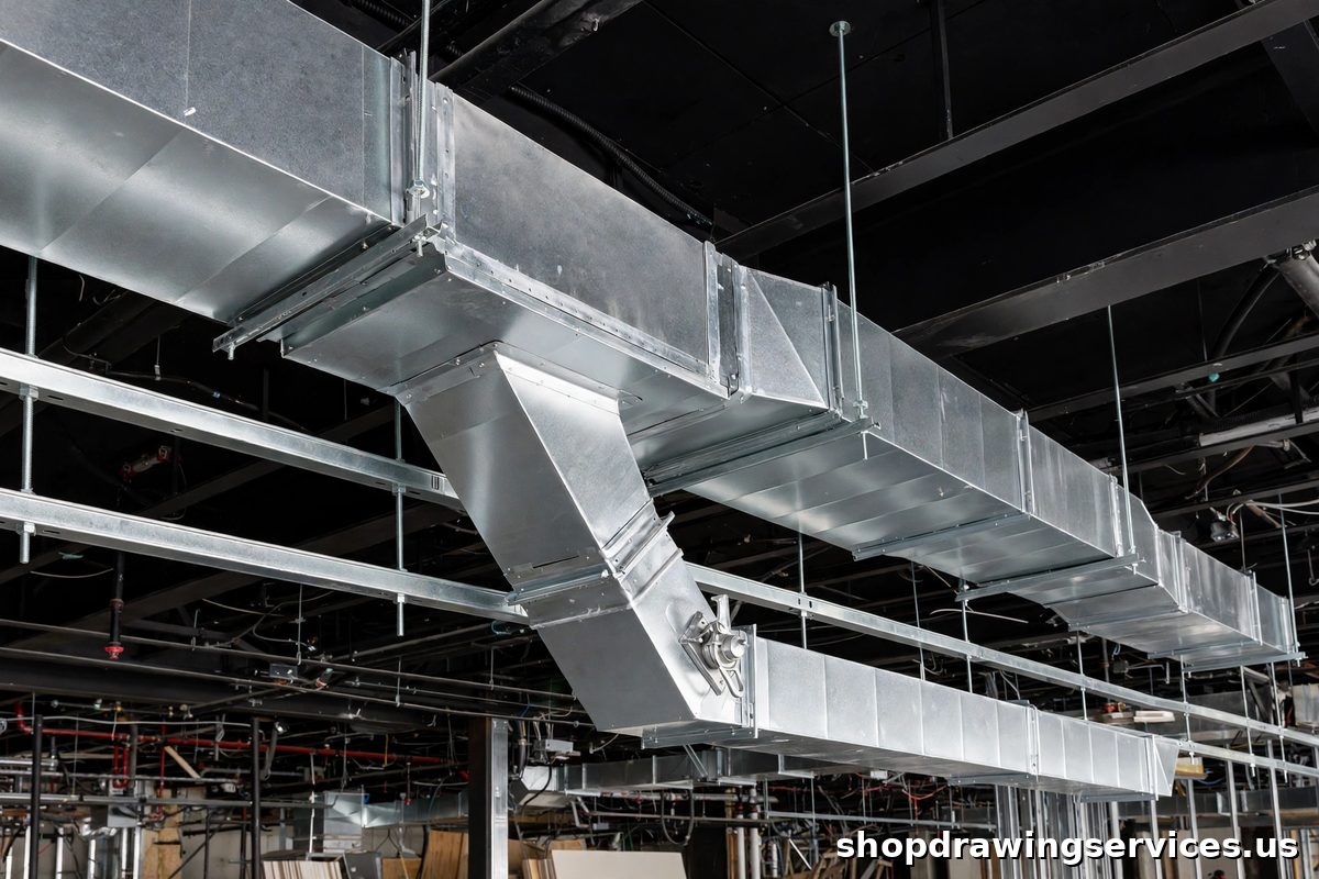
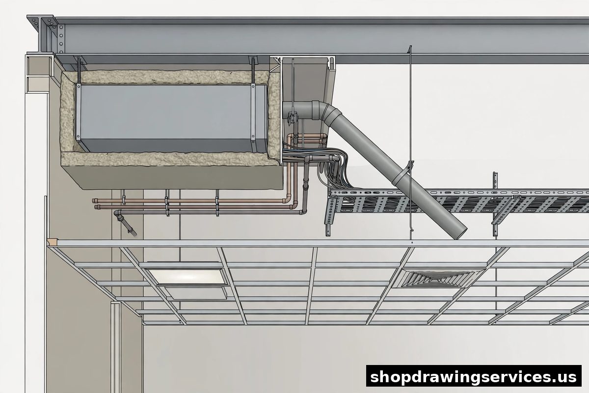
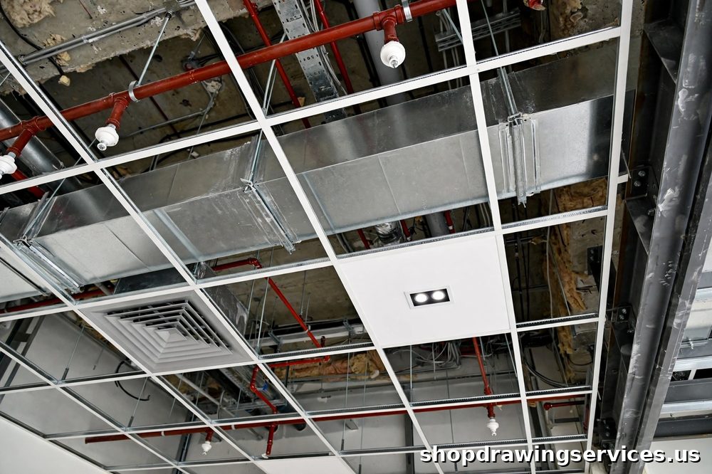
Every head must be shown where it will actually sit in the ceiling, checked against beams, ducts, lights, speakers, smoke detectors, diffusers and access panels. A head that clears on a piping plan and lands behind a beam or under a duct in the ceiling is an obstruction failure, and the drawing must show the ceiling check, not just the pipe route. The duct system is the most frequent blocker: for how duct is drawn and hung, see our guide to SMACNA duct shop drawings. A head moved one ceiling tile to clear a beam is a coordination change, and the revision must record it.
Hazard and occupancy drive the layout
Head spacing, coverage and obstruction rules follow from the hazard classification and the occupancy, as set in the design documents and the adopted NFPA 13 edition. This post publishes no spacing or coverage figure of its own: every such figure must come from the adopted edition's tables for that hazard and head type, or from the project design documents.
Risers, mains and branch lines as a readable system
The system riser carries control valves, gauges and drains; feed and cross mains carry sizes and routing; branch lines carry head positions, drops and armovers.
Artifact 2: head-layout and obstruction checklist
One reflected ceiling bay, checked head by head. Every head is marked clear or moved, with the reason for every move.
| Head | Ceiling element in the bay | Result | Action and revision note |
|---|---|---|---|
| H-01 | Open ceiling tile, no obstruction | Clear | Install as drawn |
| H-02 | Structural beam directly above | Moved | Shifted one tile east, clear of beam face, revision R2 records the move |
| H-03 | Rectangular duct crossing the bay | Moved | Dropped below duct soffit per obstruction rules, armover noted on branch line |
| H-04 | Recessed light fixture, adjacent tile | Clear | Clearance confirmed |
| H-05 | Supply air diffuser, same tile | Moved | Shifted one tile south, revision R2 records the move |
| H-06 | Smoke detector and speaker, neighbouring tiles | Clear | Positions confirmed |
Hypothetical checklist, no real project data. No head is marked clear without a named ceiling element beside it, and no head is moved without a revision note.
Seismic bracing: the part most often drawn wrong
Seismic bracing is where a sprinkler shop drawing most often fails review, usually because of a misunderstanding of what NFPA 13 actually does. NFPA 13 tells the detailer how to brace, not when bracing is required. Whether seismic protection applies at all comes from the building code, the seismic design category and the authority having jurisdiction. A drawing that presents bracing as universally required, or universally optional, is wrong in both directions.
Lateral and longitudinal are two different braces
Lateral braces resist movement perpendicular to the pipe run. Longitudinal braces resist movement along the run. A system braced in one direction only is half braced. Four-way bracing, both directions at once, is required at the locations the adopted edition names, including the top of the riser. The drawing must show where each type sits, not just call for "seismic bracing" in a general note.
The commonly cited maxima from the 2019 edition, Chapter 18, are 40 feet maximum spacing for lateral sway bracing and 80 feet maximum spacing for longitudinal sway bracing, with lateral braces required on all feed and cross mains regardless of size and on branch lines 2.5 inches and larger, and with the last brace within 6 feet of the end of a feed or cross main for lateral bracing and within 40 feet of the end for longitudinal bracing. These are layout limits from that edition, not a guarantee that every brace at those intervals has enough capacity. Confirm the figures against the adopted edition's tables before relying on them.
Braces attach to structure, not to ceiling grid or to another trade's support
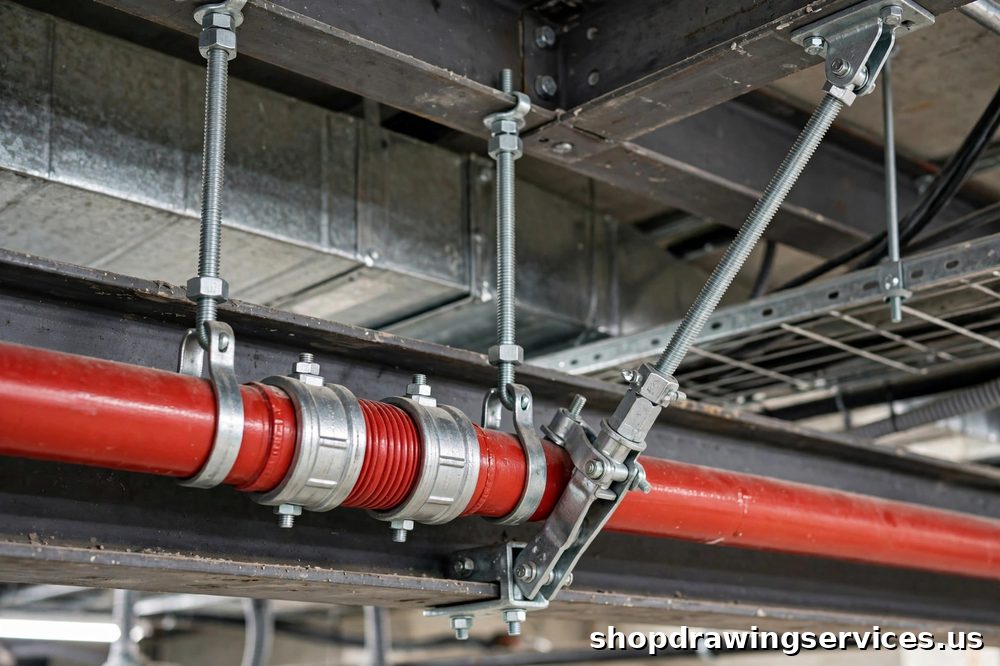
The structural member must be able to carry the combined gravity and seismic load where a brace and a hanger share a member. The brace assembly and its fasteners must be listed for the load they will actually see at their installed angle, and the zone of influence, the piping tributary to each brace, must be shown in the bracing calculations that accompany the drawings. A brace screwed to a ceiling grid, or hung from another trade's trapeze, is not a brace.
Brace loads are calculated from the adopted edition's method. In the 2019 edition, the horizontal seismic load on the piping is calculated as Fpw equals Cp times Wp, where Cp is the seismic coefficient and Wp is the weight of the piping and its contents within the zone of influence. The calculation, not the spacing table, decides whether a brace assembly at its installed angle can carry the load assigned to it. That is why the bracing calculations travel with the drawings in the submittal.
Flexible couplings, clearance and restraint complete the system
Flexible couplings belong where the adopted edition requires movement accommodation. Clearance belongs around pipe where it passes through walls and floors, so the pipe can move with the building rather than break against it. Smaller branch lines are restrained by the bracing of the mains and by flexible armovers, rather than by inventing a separate brace for every branch.
Artifact 3: riser and bracing schedule excerpt
A schedule excerpt ties the riser, the mains and the braces to one revision, so the reviewer can check the bracing without hunting through five sheets.
| Line | Size and material | Valves, gauges and drains | Bracing |
|---|---|---|---|
| System riser, base to roof | 6 in. black steel, per design | Control valve, flow switch, gauges, main drain, inspector's test connection | Four-way brace at top of riser, lateral braces per adopted edition, attached to structure |
| Feed main, Level 2 | 4 in. black steel | Floor control assembly, gauge, drain | Lateral braces 40 ft max, longitudinal 80 ft max, per 2019 edition Chapter 18, confirmed against adopted edition |
| Cross main, Level 2, Zone B | 3 in. black steel | Branch takeoffs, drain at low point | Lateral braces 40 ft max, last brace within 6 ft of pipe end, zone of influence in calculations |
| Branch lines, 2.5 in. and larger | 2.5 in. black steel | Heads on drops and armovers, per the reflected ceiling plan | Lateral bracing only, restrained by main bracing and flexible armovers |
| Branch lines, under 2.5 in. | 1.25 in. to 2 in. black steel | Heads on drops, per the reflected ceiling plan | Restrained by main bracing and flexible armovers |
The schedule is a labelled hypothetical excerpt, with no real project data.
The 7-step shop checking sequence
- Edition first: confirm the adopted NFPA 13 edition and the adopted plumbing code before drawing, and name both in the submittal.
- Zone the shafts: allocate riser and shaft space by system, show penetrations and sleeves floor by floor, freeze that zoning before routing starts.
- Set gravity lines: fix sanitary, vent and storm slopes and invert levels from the design, then route pressure plumbing and sprinklers around them.
- Lay heads on the ceiling: place every head on the reflected ceiling plan, check obstructions against beams, ducts, lights and ceiling devices, record every head move as a revision.
- Draw risers and mains as installable systems: valves, gauges, drains, backflow assemblies, cleanouts and access panels shown where they can actually be operated and serviced.
- Brace by calculation, not by habit: assign lateral, longitudinal and four-way braces from the adopted edition, with zone of influence calculations and listed assemblies at installed angles, attached to structure.
- Reconcile revisions across trades: re-run the coordination check after every accepted move, so no trade installs from a superseded head position or riser route.
What the reviewer checks before approval
The approval step that applies to a plumbing and sprinkler submittal is the same one that applies to a steel submittal. Our structural steel shop drawing submittal checklist covers what the engineer of record actually checks before approval, and the habits transfer directly. A plumbing and sprinkler reviewer adds three checks of their own. First, the shaft section and the riser diagram agree at every floor. Second, every head on the reflected ceiling plan has a named ceiling element beside it, clear or moved. Third, every brace on the schedule has a zone of influence calculation behind it and a structural attachment in front of it.
When those three checks pass, the submittal is ready for the first review. When they do not, the drawing goes back, and the delay costs the same as every other submittal delay: pipe that cannot be cut and a ceiling that cannot be closed.
For plumbing and fire protection shop drawings built to the adopted code and the adopted NFPA 13 edition, see our plumbing and fire protection services or contact us with your design documents.