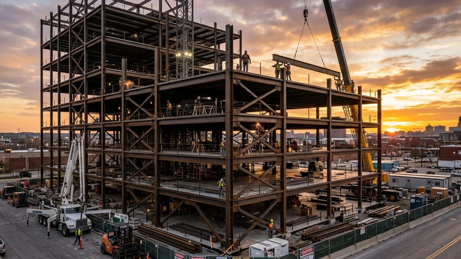
A duct shop drawing is a fabrication instruction, not a layout sketch
A design drawing shows a duct system at a size and a route. A duct shop drawing tells the sheet metal shop exactly what to cut, fold, join and hang, piece by piece. If your submittal only redraws the design layout at a larger scale, it has not done the shop drawing job, and it is the submittal most likely to come back marked revise and resubmit.
Who this is for: sheet metal detailers, HVAC subcontractors, MEP coordinators and fabricators who turn a coordinated model into duct that fits, seals and passes inspection on the first review. The short answer: a duct shop drawing that passes review states the pressure class per system, names every seam and joint type, draws every transition and fitting as a dimensioned fabricated piece, places every damper where it can be reached and operated, schedules every hanger, states the sealing class, and arrives with a fabrication cut sheet whose piece marks and quantities match the drawing at the same revision.
The standard behind the drawing: ANSI/SMACNA 006-2020
The industry standard for duct construction in the United States is the SMACNA HVAC Duct Construction Standards, Metal and Flexible. The current edition is the fourth edition, ANSI/SMACNA 006-2020, which supersedes the 2006 third edition. It sets construction classes, material and gauge selection, seam and joint construction, reinforcement, sealing, hangers and supports, and leakage expectations for rectangular, round and flat oval duct. The standard does not hand you one duct detail for the whole building. It gives you tables that tie gauge, reinforcement, joint type and hanger spacing to the pressure class and the duct size, and your drawing applies those tables system by system, size by size.
One point belongs here before anything else: the project specification, not this post, sets the construction class, pressure class, material and sealing class for the job at hand. This post explains what SMACNA requires on the drawing and how a reviewer checks it. It sets no gauge, spacing or leakage figure for your project.
For the coordination model this fabrication drawing is built from, see our guide to MEP coordination in tight ceiling plenums. That post covers the clash detection workflow that clears duct, pipe and cable tray in the same space. This post starts where that one stops: the coordinated route is settled, and now the shop has to fabricate from it.
Pressure class and the construction schedule, per system
Start every duct shop drawing set with a construction schedule that breaks the job down by system. Supply, return, exhaust and outside air systems do not automatically share a pressure class, and a single schedule that covers the whole building without a per-system break is a reviewer trap.
For each system, the schedule states the pressure class, the construction class, the material, the sealing class and the leakage class the system is tested to where the specification requires testing. It also states the duct shape it covers, because rectangular, round and flat oval duct do not take the same construction. A reviewer reads this schedule first.
Gauge, reinforcement and joint type follow from the class and the duct size, per the SMACNA tables for that class. Get the class wrong and every gauge, joint and reinforcement on the set is wrong with it. Before drawing a single fitting, confirm the pressure class, construction schedule and sealing class per system from the specification, and confirm the duct size and route still match the coordinated model, including insulation thickness and hanger clearance.
Seams and joints: name the type, match it to the class
A joint drawn without a type is a fabrication question the shop should have answered before cutting. Every seam and joint on the drawing carries its type, matched to the pressure class and duct size it is rated for.
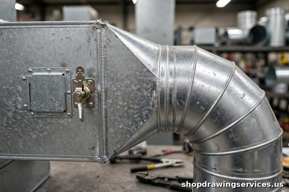
For rectangular duct, the longitudinal seam is commonly a Pittsburgh lock, with other seam types used where the class and size call for them. Transverse connections include slip and drive, standing seam, slide-on flange and companion angle connections. Each is rated for a pressure class and a duct size range in the SMACNA tables, and each has a different installed cost, a different leakage behaviour and a different fabrication step.
Round and flat oval duct have their own joint and seam conventions, and the same rule applies: name the type, and use it inside the class it is rated for.
Transitions and fittings, drawn as pieces
Transitions and fittings are where a duct shop drawing earns its keep, and where a redrawn design layout gives itself away. A transition is not a centre line with two sizes written on it. It is a fabricated piece with its own geometry, its own piece mark and its own dimensions, drawn so the shop can cut it without re-deriving anything from the design drawing.
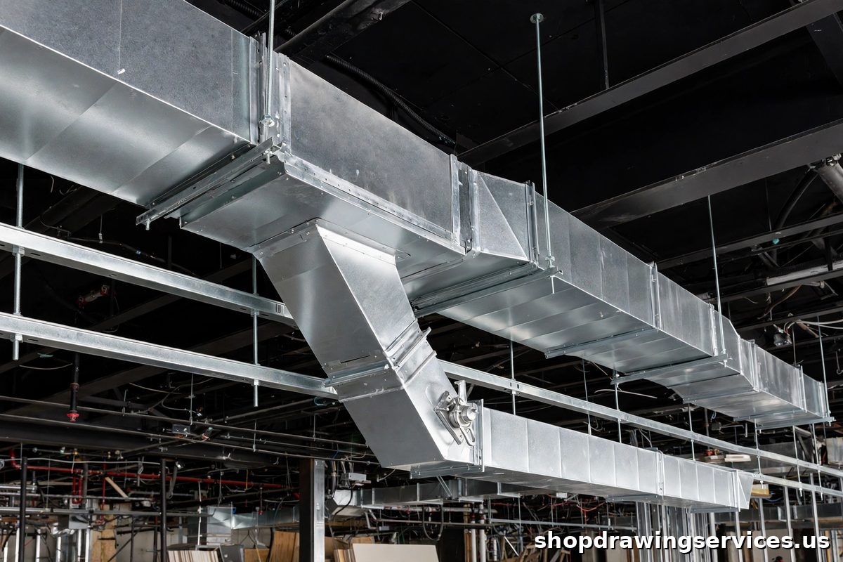
Draw every transition, offset, elbow, branch takeoff and reducer as a dimensioned fabricated piece. Concentric and eccentric transitions get their own callouts, because the shop cuts them differently. An elbow carries its turning vanes where the standard and the specification require them, and the vane callout is on the drawing.
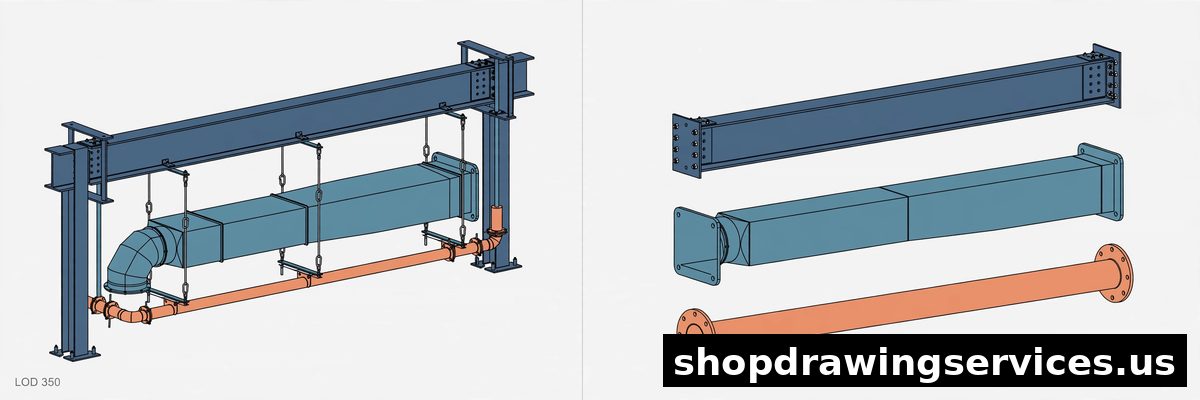
The artifact below is a shop drawing excerpt for a short straight run. It is labelled hypothetical, with no real project data, and it shows what a reviewer expects to see on the drawing itself: every piece marked, every joint type named, and the access panel called out at its real location.
Artifact 1: Duct shop drawing excerpt, hypothetical
Piece mark | Piece | Size and length | Joint and seam | Notes |
|---|---|---|---|---|
D-101 | Straight duct, supply | Rectangular, 3,000 mm long | Pittsburgh lock seam, slide-on flange joints | Gauge and reinforcement per schedule for this system and size |
D-102 | Concentric transition | Reduces to smaller size over 900 mm | Same seam and joint types as D-101 | One fabricated piece, own piece mark |
D-103 | Branch takeoff with volume damper | Branch size per design | Takeoff per SMACNA tables for this class | Volume damper at branch, access panel on duct face below |
H-101, H-102 | Hangers, trapeze type | Two hangers on run D-101 | Rod and strap per hanger schedule | Spacing per SMACNA tables, attachment to structure confirmed |
Notice what the excerpt does not do. It lists no gauge number, hanger spacing or leakage figure, because those come from the SMACNA tables for the stated pressure class and duct size and from the project specification.
Dampers: drawn where they operate, with access
Volume dampers belong at branches and takeoffs, where the air balance actually happens. Fire and smoke dampers belong at rated penetrations, with their ratings and access shown. Balancing dampers belong where the air balance requires them. Every damper needs its type, its size, its location and its access panel on the drawing, because a damper nobody can reach cannot be balanced, tested or inspected.
Access is part of the damper, not an afterthought. An access door or panel is shown at its real location, sized for the damper it serves, and reachable from the space the installer and the balancer will actually stand in. A damper above a hard ceiling with no access panel is a damper that will never be adjusted. Fire and smoke damper ratings, listings and installation requirements belong to the project specification, the damper listing and the applicable fire code, and this post states no rating, listing or installation rule for them. The drafting rule is: show the damper, show its rating callout as specified, and show the access.
Hangers and supports on the drawing, not left to the field
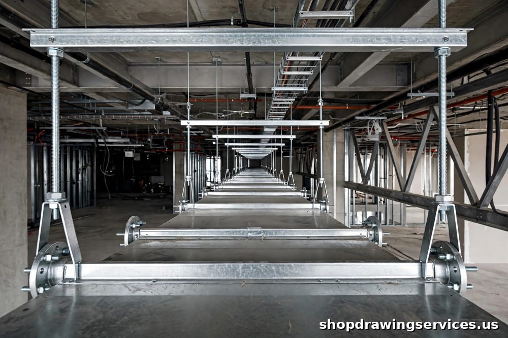
A duct run with no hanger schedule is an installation guess. Hangers and supports are shown on the drawing, with hanger type, rod and strap sizing, and spacing per the SMACNA tables for the duct size and class. Trapeze hangers and individual hangers are different choices with different load paths, and the drawing states which one is used where. Attachment to structure is shown, not assumed, and confirmed with the structural coordination. A hanger attached to the wrong structure is a coordination failure, and it is the kind of failure the coordination model exists to catch before the shop cuts anything.
Seismic restraint is called out where the project requires it, rather than assumed. Restraint requirements are project and jurisdiction specific, and this post states none of them. The drafting rule is that the requirement, where it applies, appears on the drawing as a specified item, not as a field decision.
Sealing, leakage class, access, insulation and lining
Sealing is a system decision, not a shop preference. The drawing states which joints and seams are sealed, with what sealant class, and what leakage class the system is tested to where the specification requires testing. An unsealed low pressure assumption on a higher class system is a performance failure, not a drafting shortcut.
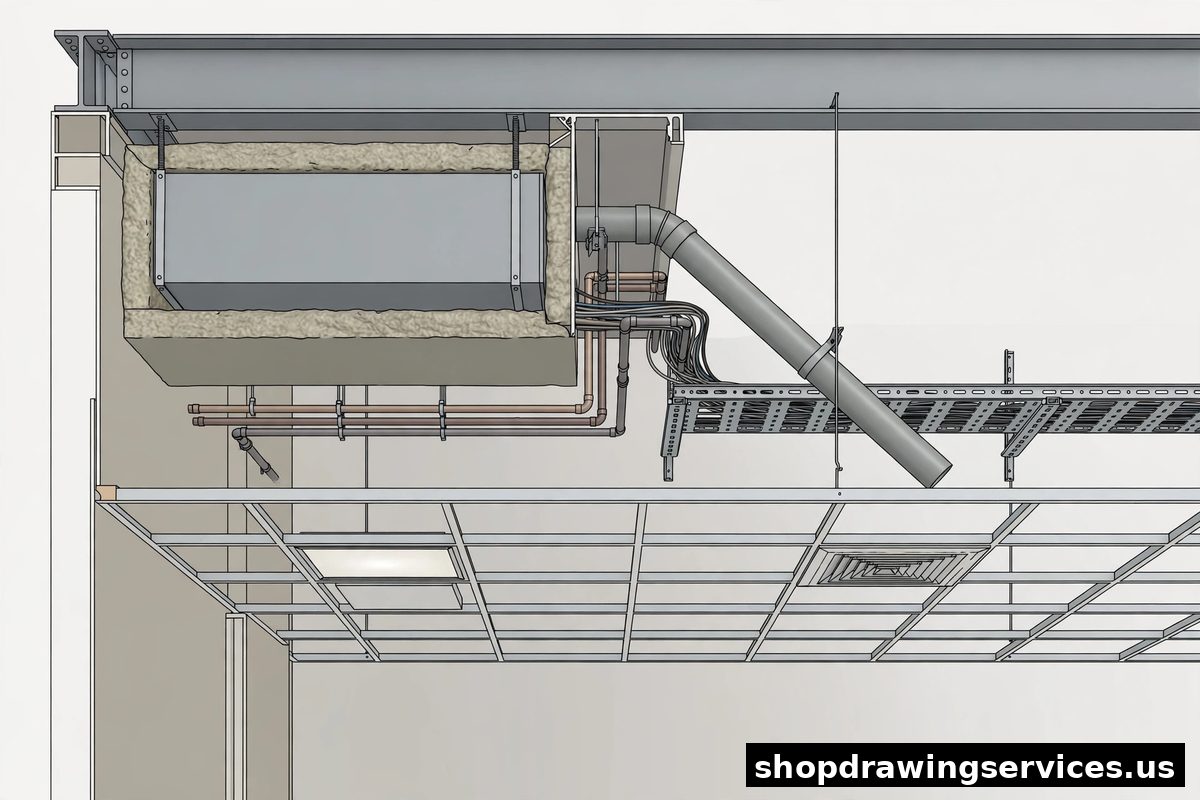
Access, insulation and lining are kept distinct on the drawing, because they are distinct scopes with distinct dimensions. Access doors and panels are shown for dampers, coils, fans and cleaning at their real locations. External insulation and internal liner are shown as separate scope, with liner fastening and edge treatment called out. A lined duct dimensioned to its outside size will not fit its inside airflow.
Fabrication cut sheets: the shop floor document
The cut sheet is the bridge between the shop drawing and the cutting table. One line per piece, with piece mark, duct size, length, material and gauge, seam and joint type, reinforcement, damper and accessory callouts, and quantity. The shop cuts from the cut sheet, so the cut sheet has to be right, and it has to match the drawing. Two checks matter most. Piece marks on the cut sheet match piece marks on the shop drawing, and quantities on the cut sheet match the run, with no piece cut twice and none missed.
Three traps catch cut sheets again and again. A cut sheet generated from the design model without the shop drawing review step, which carries design sizes that were never shop-checked. A cut sheet with no revision link to the shop drawing revision, so a revised drawing leaves old pieces in the shop. A cut sheet that lists straight duct but omits fittings, transitions and dampers, so the shop cuts the easy pieces and discovers the hard ones at installation.
The artifact below is a fabrication cut sheet excerpt for the same hypothetical run as Artifact 1. It is labelled hypothetical, and it shows the revision column that ties the cut sheet to the shop drawing revision. When the drawing revises, the cut sheet revises with it, and the shop knows which rows are current.
Artifact 2: Fabrication cut sheet excerpt, hypothetical
Piece mark | Description | Size | Length | Material and gauge | Seam and joint | Qty | Rev |
|---|---|---|---|---|---|---|---|
D-101 | Straight duct, supply | Rectangular | 3,000 mm | Galvanized steel, gauge per schedule | Pittsburgh lock, slide-on flange | 1 | R1 |
D-102 | Concentric transition | Reducing, rectangular | 900 mm | Galvanized steel, gauge per schedule | Pittsburgh lock, slide-on flange | 1 | R1 |
D-103 | Branch takeoff with volume damper | Branch size per design | Per drawing | Galvanized steel, gauge per schedule | Takeoff per SMACNA tables | 1 | R1 |
H-101 | Trapeze hanger, complete | Per hanger schedule | Per drawing | Rod and strap per schedule | Not applicable | 1 | R1 |
H-102 | Trapeze hanger, complete | Per hanger schedule | Per drawing | Rod and strap per schedule | Not applicable | 1 | R1 |
Reconcile this cut sheet against the drawing before release to the shop floor. Every piece mark on the drawing appears once on the cut sheet, and every row on the cut sheet appears once on the drawing, at the same revision.
The 7-step shop checking sequence
Run this sequence on every duct shop drawing set before it leaves the office. It is the difference between a submittal and a resubmittal.
Class first. Confirm pressure class, construction schedule and sealing class per system from the specification.
Size and route against coordination. Confirm duct size and route still match the coordinated model, including insulation and hanger clearance.
Joints and seams per class. Assign seam and joint types from the SMACNA tables for that class and size.
Fittings as pieces. Draw every transition, offset, elbow, takeoff and reducer as a dimensioned piece with a piece mark.
Dampers and access. Place every damper with type, rating where applicable, and a reachable access panel.
Hangers on the drawing. Schedule hanger type, size and spacing, and confirm the attachment structure.
Cut sheet reconciliation. Reconcile piece marks, sizes and quantities between shop drawing and cut sheet, and tie both to the same revision.
For what a shop drawing still is when a model exists, and why the drawing remains the contract document even in a BIM workflow, see our guide to shop drawings vs fabrication drawings vs erection drawings. The model coordinates the work. The shop drawing instructs the fabrication.
Pre-submittal checklist for a duct shop drawing set
Run this checklist as the last step before submission. A set that passes it is a set the reviewer can approve.
Pressure class, construction schedule and sealing class stated per system
Gauge, reinforcement and joint type from the SMACNA tables for the stated class and size
Every longitudinal seam and transverse joint named by type
Every transition, offset, elbow, takeoff and reducer drawn as a dimensioned piece with a piece mark
Every damper shown with type, size, location and a reachable access panel
Fire and smoke damper ratings and access shown as specified
Hanger type, size and spacing scheduled, attachment structure confirmed
Sealing class stated, leakage class stated where testing is specified
Access doors shown at real locations for dampers, coils, fans and cleaning
Insulation and liner shown as separate scope, liner thickness accounted for
Cut sheet reconciled to the drawing: piece marks match, quantities match, no piece cut twice, none missed
Cut sheet revision tied to the shop drawing revision
Neighbouring sprinkler and plumbing runs checked against the coordination model
The approval step itself is the same one that applies to a steel submittal. For what the engineer of record actually checks before approval, see our structural steel shop drawing submittal checklist. The trade is different. The review discipline is the same.
What gets a duct submittal returned
Most returned duct submittals fail on the same handful of points, and every one of them is visible on the drawing before it is sent. A construction schedule with no per-system break. A joint type drawn without a name, or used outside its pressure class. A transition drawn as a centre line instead of a fabricated piece. A damper with no access panel. A run with no hanger schedule. A sealing class left implied. A cut sheet that does not match the drawing, or that carries no revision link to it.
None of these is a hard problem. All of them are easy to miss when the set is rushed, and all of them cost a review cycle, a resubmittal, and a week of fabrication time.
Our HVAC and mechanical shop drawing services cover duct, piping and equipment detailing to SMACNA standards, coordinated against the project model and delivered with fabrication cut sheets the shop can cut from. Browse the full range of shop drawing services, or contact us with a scope and a specification.